
User Manual


Apollo3 Blue Datasheet
DS-A3-0p9p1 Page 218 of 909 2019 Ambiq Micro, Inc.
All rights reserved.
7.3.1 Paired-Quad Device Operation (QUADCMD)
Using a single serial, dual, quad, or octal device is fairly straightforward since all data and commands sent
to the device are transmitted and received as a string of serialized bytes. On the surface, using a pair of
quad devices would appear to work like a single octal device, but in actuality, it is a bit more complex since
instruction and address phase bytes must be replicated as nibbles to each device while data phases of the
transfer are split across devices. To simplify the use of paired-quad devices by software, the MSPI
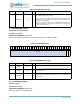
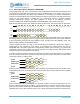
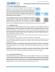
controller automatically manages the nibble replication as shown in the following sequences
(instruction=0x0B (read), address=0x12345678, data=0xABCDEF01 with 2 turnaround cycles).
Note that the address phase of the paired-quad looks identical to the quad device while the data phase
looks identical to the octal device. The MSPI module handles this automatically based on the DEVCFG
field setting instead of requiring software to configure each part individually (each part could be configured
by first programming the lower lane using SERIAL0 mode, the upper lane using SERIAL1 mode, then
switch the MSPI interface into QUADPAIR mode).
However, register operations to a pair of quad devices must be handled as if writing both devices in
parallel (data is also replicated to each device). To accomplish this, software should also set the
QUADCMD field in the CTRL register when writing/reading registers (versus memory) in a paired-quad
configuration, which lets the controller know that the operation is a register operation that requires the full
instruction and data to be replicated to both devices.
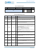
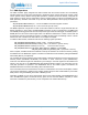
Consider the following operations to write an 8-bit register and read the 8-bit device status for an individual
quad, an octal part, and a pair of quad devices (the write sequence is 0x81 0xAB which is a write volatile
configuration register on a Micron part):
Notice that each of the devices receives the same sequence as an individual quad part. Likewise, when
reading status from a pair of quad devices, the status from each device must be read instead of a single 8-
bit status:
Again, software must set the QUADCMD bit in the CTRL register to ensure that read data from each
device is captured independently. In addition, for read operations the controller will de-interleave the read
bytes and return them in the RX FIFO as 0xCDAB (device 0 in byte 0, device 1 in byte 1) and to maintain
similarities when running with quad/octal devices, only a single byte write/read operation should be issued.
0x0
0xB 0x1
0x2 0x3
0x4 0x5
0x6 0x7 0x8
0xA
0xB 0xC
0xD 0xE
0xF 0x0
0x1
QUAD
0x0
0xB 0x1
0x2 0x3
0x4 0x5
0x6 0x7 0x8
0xA
0xC 0xE
0x0
QUAD
0
0x0
0xB 0x1
0x2 0x3
0x4 0x5
0x6 0x7 0x8
0xB
0xD 0xF
0x1
QUAD
1
0x0
0x1 0x3
0x5 0x7
0xA
0xC 0xE
0x0
OCTAL
74
0xB
0x2 0x4
0x6 0x8
0xB
0xD 0xF
0x1
OCTAL
30
0x8
0x1 0xA
0xB
QUAD
0x8
0x1 0xA
0xB
PAIRQUAD0
0x8
0x1 0xA
0xB
PAIRQUAD1
0x81
0xAB
OCTAL
0x8
0x5 0xA
0xB
QUAD
0x8
0x5 0xA
0xB
PAIRQUAD0
0x8
0x1 0xC
0xD
PAIRQUAD1
0x85
0xAB
OCTAL