
User Manual


Apollo3 Blue Datasheet
DS-A3-0p9p1 Page 180 of 909 2019 Ambiq Micro, Inc.
All rights reserved.
register meets the data criteria. Because the MCU access to the interface is 32b wide, only the word count
of the selected THR is used, and the low order bits of the FIFOWTHR or FIFORTHR are ignored.
During the transfer, the TOTCOUNT register is decremented to reflect the number of bytes transferred.
For BLE write operations (data written from BLEIF into the BLE Core), the THR trigger will activate when
the write FIFO contains FIFOWTHR[5:2] free words. If the remaining DMA transfer size is less than this,
only the needed number of words are transferred.
For BLE read operations (data read from BLE Core from the BLEIF), the THR trigger will activate when the
read FIFO contains FIFORTHR[5:2] words of valid data. If the remaining DMA transfer size is less than the
RTHR words, then the CMDCMP trigger can be enabled to transfer the remaining data. If the CMDCMP
trigger is disabled, and the number of bytes in the read FIFO is greater to or equal to the current
TOTCOUNT, a DMA transfer of TOTCOUNT will be done to complete the DMA operation. Note that this
mode requires that the THR trigger be enabled as well.
The CMDCMP trigger activates when the command is complete, and will transfer the lesser of the
TOTCOUNT or the number of bytes in the read FIFO. Note, this trigger is not needed for write operations,
and the THR trigger should be used in this case. If a read operation is done, and the THR trigger is
disabled, and only the CMDCMP trigger is enabled, and the transaction size is greater than the FIFO size
(32 bytes), the module will hang, as there is not trigger to cause a DMA operation, and the logic will pause
the interface until there is room within the read FIFO to store data.
If DMA transfer size is matched to the BLEIF transaction size, it is recommended to program both the
FIFORTHR and FIFOWTHR to 0x10 (16 bytes) and only enable the THR trigger.
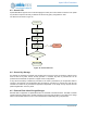
6.2.1.2 Command Queue
The BLEIF module can also fetch register write data from SRAM or FLASH, and update the registers as if
the write was performed via the MCU. Register data is stored as a doublet of 2 words. The first word is the
register address offset, word aligned. The second word is the write data value. Once enabled, the
command queue (CQ) will fetch the address, and perform a write to the register If no command is started
by the register write, the next doublet will be fetched by the CQ. If a command is started, the transaction
will run, and the CQ will continue fetching when the module is idle. No pre-fetching is done via the CQ, and
the register write operations are performed in series with the transactions. This allows a predictable path
for execution of commands.
6.3 BLEIF Registers
BLE Interface
INSTANCE 0 BASE ADDRESS:0x5000C000
Registers associated with the BLE Core interface module. The BLEIF module is used to interface with the
embedded BLE Core module and supports read and write transactions to the BLE Core. It also contains
the power sequencing control which will switch the BLEH power to the BLE core when needed. The
registers control the speed of the interface, mode of operation and other parameters for the transaction. It
is recommended to run at 16MHz with a mode of 3 on the SPI interface. Prior to use and access, the BLE
module domain must be powered up through registers within the power control module. Once powered,
the power state machine must be enabled to allow power control of the BLE Core module.