
User Manual


Apollo3 Blue Datasheet
DS-A3-0p9p1 Page 179 of 909 2019 Ambiq Micro, Inc.
All rights reserved.
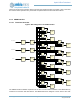
▪ External Power Amplifier support
▪ Integrated Balun and antenna matching network
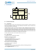
6.2 Functional Description
The BLE subsystem is a fully integrated system providing autonomous clock and power management. The
subsystem is accessed via the BLE interface block. Software leverages the fully HCI compliant interface
for Bluetooth operation. A series of proprietary HCI commands are also leveraged to provide additional
performance and low power operation.
The BLE subsystem must first be enabled by issuing an enable to the BLE feature enable register (Section
3.8.2.7 on page 128). The device is then enabled by setting the BLEL controller device enable field in the
power controller device register (DEVPWREN Register in System Core chapter). Once the BLEL domain
is powered up through the BLEL enable, software can enable the power state machine within the BLE
interface module to allow the BLEH power domain to be activated.
Communication between the BLE core and the MCU is done through the BLE interface (BLEIF) module.
This module uses a similar interface as the IOM module. This module will facilitate the data transfer to and
from the BLE core and supports direct and DMA data transfer mechanisms. The module also contains the
power sequencing logic to control the power domains used for the BLE Core. This logic will control the
initial power on, as well as power down of domains during sleep mode automatically.
The BLEIF contains flow control mechanisms that allow write transactions under control of the BSTATUS
signal from the BLE core, and will similarly gate read transactions using the BLEIRQ signal from the BLE
Core. These are enabled via the BLEIF_MSPICFG register fields of RDFC and WTFC.
The BLE subsystem will automatically enter into a low power sleep mode when no active commands are
issued and no active Tx/Rx events.
6.2.1 Data Transfers
Data transfers to and from the BLE core are done using HCI packets. The HCI packet structure is used for
both data input and output, For event frames read from the BLE Core, an optional mode is available to
prepend a 2 byte length to the start of the packet. This mode is enabled with a vendor specific command.
The HCI commands and packet formats are detailed in the Bluetooth specification, version 4.2, volume 2,
part E, sections 7.8.1 through 7.8.46 (LE Controller commands). Additional vendor specific commands are
also available for operations such as setting the frame mode, setting sleep mode and other BLE Core
specific commands.
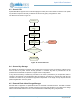
6.2.1.1 DMA data transfers
DMA transfers are enabled by configuring the DMA related registers, enabling the DMA channel, and then
issuing the command. The command will automatically fetch and store the data associated with the
command without MCU intervention. The DMA channel is enabled via the DMAEN field in the
REG_BLEIF_DMACFG register.P2M DMA operations transfer data from peripheral to memory, and are
used in BLEIF READ operations. M2P DMA operations transfer data from memory to peripheral, and are
used in BLEIF write operations. DMA transfer size is programmed into the REG_BLEIF_DMATOTCOUNT
register and supports up to 4095 bytes of data transfer. The DMA transfer size is independent from the
transaction size, and allows a single DMA setting to be used across multiple commands. The direction of
DMA data transfer must match the command. The DMAEN field in the REG_BLEIF_DMACFG register
enables/disables the DMA transfer capability and must be set last when configuring the DMA, generally
prior to sending the command.
The DMA engine within the module will initiate a transfer of data when a trigger event occurs. There are 2
type of triggers available, threshold (THR) and command completion (CMDCMP). The THR trigger will
activate when the threshold programmed into the FIFOWTHR or FIFORTHR in the REG_BLEIF_FIFOTHR