
User Manual


Apollo3 Blue Datasheet
DS-A3-0p9p1 Page 178 of 909 2019 Ambiq Micro, Inc.
All rights reserved.
6. BLE Module
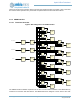
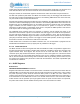
Figure 11. Block Diagram for the BLE Module
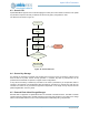
6.1 Functional Overview
6.1.1 Introduction
The Apollo3 Blue MCU includes a low power Bluetooth low energy subsystem. The BLE controller and
host can be configured to support up to eight simultaneous connections. Secure connections and
extended packet length are also supported.
The BLE subsystem contains a 2.4 GHz RF transceiver, modem, baseband and 32-bit processor. It
supports an external 32 MHz crystal clock source as well as an internal 32 MHz RC oscillator clock source.
The 32 MHz crystal is required as the frequency reference for the radio and also as the main clock source
for the controller blocks. The internal 32 MHz RC can be used as a clock source for the RF processor if the
requirements allow for lower precision and lower power operation. Driving an active clock into BLE crystal
pins is not supported, as the crystal pins do not support active components.
The BLE subsystem provides a Host Controller Interface (HCI) to the host.
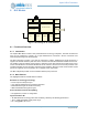
6.1.2 Main Features
The highlighted features of the BLE are as follows:
Bluetooth 5 Low Energy Technology
▪ Full on-chip HCI Transport Layer
▪ Up to eight (8) simultaneous connections supported
▪ Extended PDU length and enhanced security
▪ AES-128 Hardware Encryption Engine
Secure Firmware Over-the-Air Updating
▪ Per application, function or configuration
High Performance RF
▪ -94 dBm Bluetooth low energy transceiver sensitivity, selectivity and blocking performance
▪ -20 to +4 dBm transmitter output power range
▪ TX: 3 mA @0dBm, RX: 3 mA
Bus
Interface
Regs
INTs
Pwr Mgt
BLE 32b Controller
ModemRF Baseband
Security
128kB ROM
42kB RAM
RC
32MHz
XTAL
32MHz
Cmd
Queue
DMA