
User Manual


Apollo3 Blue Datasheet
DS-A3-0p9p1 Page 176 of 909 2019 Ambiq Micro, Inc.
All rights reserved.
5. DMA
5.1 Functional Overview
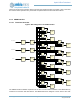
The Apollo3 Blue MCU supports DMA capability for the following peripheral controllers:
▪ SPI Master
▪ I2C Master
▪ PDM
▪ ADC
▪ MSPI
▪ BLE
▪ Security
DMA is supported from peripheral to SRAM and SRAM/Flash to peripheral. DMA transactions to/from
SRAM occur concurrently to CPU instruction/data accesses as long as the accesses are to different
physical banks of memory. Accesses to the same physical bank are arbitrated in hardware. Similarly,
accesses to Flash occur concurrently to other DMA transactions to SRAM. CPU accesses (via cache miss
or uncacheable access) are arbitrated with DMA accesses in hardware. There is hardware support to
manage DMA request arbitration, physical memory resource arbitration, clocking and power management.
DMA configuration is programmed via the respective peripheral controller interface. Each peripheral has
the same DMA capability with some minor exceptions where peripheral specific behavior is required. For
example, for configuring the DMA transaction trigger, there are different trigger options for each peripheral
depending on the mode of operation.
5.1.1 General Usage
The DMA controller is enabled at reset and no chip-level initialization is required (DMA may be disabled by
clearing the DMA_ENABLE bit in the APBDMACTRL register in the CONTROL register block). The DMA
controller automatically manages byte-aligned addresses in memory and non-word transfer lengths. While
peripherals have the ability to DMA large blocks of data to/from memory, individual DMA transfers are
performed at a granularity of 1-16 bytes per transfer.
To utilize DMA, software should program the peripheral's DMA control registers to enable data transfer to/
from the FIFOs that would normally have been done by software. DMA-capable peripherals have been
updated with additional interrupts to notify software of transfer and DMA completion events. Each
peripheral also has the following common registers:
▪ "DMATARGADDR: Specifies the SRAM or flash address for the start of the transfer. As the transfer pro-
ceeds, the peripheral will update this address to track the current DMA location in memory.
▪ "DMATOTCOUNT: Specifies the total number of bytes to be transferred to/from memory. This value will
also decrement throughout the transfer.
▪ "DMABCOUNT: Specifies the DMA "burst" size or number of bytes to be transferred each time a DMA
access is triggered in the peripheral. For most optimal efficiency, this should be set to 16 or 32 bytes
which would correspond to one or two actual transactions to memory.
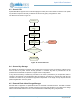
Each peripheral also has registers to control when DMA transfers are initiated. Upon reaching the DMA
threshhold, the device will request a DMA transfer and the DMA engine will perform the required number of
read/write operations to move the data to/from SRAM or flash memory. Peripherals will typically issue
multiple DMA read/write operations to complete a longer DMA transfer and each peripheral has a few
configuration options to help software manage the flow of data. For instance, a peripheral with a 16-word
FIFO might be configured to transfer 4 words each time the FIFO reaches 4 entries while the CPU is
awake in order to flush data as quickly as possible while during periods of deep-sleep, the peripheral may
be configured to transfer 8-12 words at a time once the FIFO reaches 12-16 entries in order to minimize
the wake time of the SRAM banks.