
User Manual


Apollo3 Blue Datasheet
DS-A3-0p9p1 Page 156 of 909 2019 Ambiq Micro, Inc.
All rights reserved.
▪ 2 instances of 512 KB flash Memory (up to 1 MB total)
▪ 16 KB Flash cache (2-way set-associative/Direct Mapped, 512 entry, 128b linesize)
▪ 16 KBytes OTP
- 8 KBytes contain factory preset per chip trim values.
- 8 KBytes for customer use, including flash protection fields
▪ Flash Protection specified in 16 KB Chunks
- 64 OTP bits specify Write Protected Chunks
- 64 OTP bits specify Read Protected Chunks
- A Chunk is Execute Only if Both Corresponding Protection Bits Specified
- OTP bits Specify Debugger Lock Out State
- OTP bits Can Protect SRAM Contents From Debugger Inspection
▪ External Flash with XiP (via MSPI) with cache support (up to 64MB)
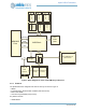
3.9.2 Functional Overview
The Apollo3 Blue MCU Integrates up to 1024 KBytes of on-board flash memory and 16 Kbytes of one time
programmable memory. These two memories are managed by the APB flash controller for write
operations.
During normal MCU code execution, the Flash Cache Controller translates requests from the CPU core to
the Flash Memory instance for instruction and data fetches. The Controller is designed to return data in
zero wait-states when accesses hit into the cache and can operate up to the maximum operating
frequency of the CPU core. On cache misses, the controller issues miss requests to the Flash memory
controller.
The Flash Memory Controller facilitates flash erase and programming operations. When erase or
programming operations are active, instructions cannot be fetched for execution from the Flash memory,
so the on-chip SRAM would have to be used for code execution. The cache controller ensures these
operations are synchronized. To facilitate the management of flash updates and OTP programming, a
number of flash helper functions are provided in the boot loader ROM.
The boot loader ROM contains approximately 4 KB of instructions that are executed upon power up of the
processor. Once a valid reset vector is establish at offset zero in the flash memory, the boot loader
transfers control to users application by issuing a POR type reset which causes the core to enter the reset
vector in flash.
The Apollo3 Blue MCU supports secure boot leveraging the SecureSPOT technology. The root of trust for
the secure boot is the boot ROM and the Ambiq secure boot loader. Secure boot, if enabled, will be
invoked on each boot and reset cycle. Some secure boot functionality is conditionally supported on reset
leveraging the SECBOOTONRST configuration in OTP. More details on the Apollo3 Blue MCU security
features are described in “Security” on page 173 and also in the Ambiq Apollo3 Blue MCU Security
Whitepaper.