
Data Sheet


TB6612FNG
4
2007-06-30
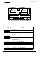
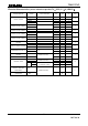
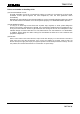
H-SW Control Function
Input Output
IN1 IN2 PWM STBY OUT1 OUT2 Mode
H H H/L H L L Short brake
H H L H CCW
L H
L H L L Short brake
H H H L CW
H L
L H L L Short brake
L L H H
OFF
(High impedance)
Stop
H/L H/L H/L L
OFF
(High impedance)
Standby
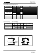
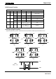
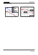
H-SW Operating Description
・To prevent penetrating current, dead time t2 and t4 is provided in switching to each mode in the IC.
VM VM
VM
M
VM
GND
<ON>
t5
M
VM
GND
<OFF>
t4
M
GND
M
GND
<Short brake>
t3
M
GND
<OFF>
t2
<ON>
t1
OUT2
OUT1
OUT1
OUT1
OUT1
OUT1
OUT2
OUT2
OUT2
OUT2
GND
VM
OUT1
Voltage wave
t1
t2
t3
t5
t4