
Data Sheet


VS1000 Datasheet
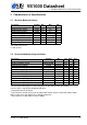
3 CHARACTERISTICS & SPECIFICATIONS
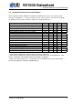
3.6 Analog Characteristics of CVDD Voltage Monitor
Parameter Symbol Min Typ Max Unit
Trigger voltage CMON 1.40 1.53 V
Hysteresis 2 mV
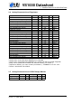
3.7 Power Button Characteristics
When the PWRBTN input is high the internal regulators get start signal so that they activate
and the vs1000 starts normal operation. Unless otherwise noted: VHIGH = 4.0..5.3 V
Parameter Min Typ Max Unit
PWRBTN pulse 10 ms, 2.3 V
Note: PWRBTN is both an analog input pin and a digital input pin, so the voltage on the pin
should not exceed 3.6 V.
Note: PWRBTN generates a RESET if it is continuously asserted for approximately 5.6 sec-
onds.
If the application is intended to turn on automatically when power is applied instead of a press
of a power button, a capacitor and a suitable resistor divider can generate a pulse to PWRBTN
from the supply voltage. However, care must be taken that the voltage limit of 3.6 V is not
exceeded.
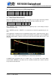
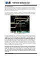
Figure 1: Typical PWRBTN pulse and minimum requirement
A PWRBTN pulse generated from a 5 V VHIGH using a 1µF capacitor and a 56kΩ/100kΩ
resistor divider. PWRBTN is at or above 2.3V for a duration of about 22 ms, which is well over
the guaranteed activation time.
Version: 1.5, 2016-06-09 8