
Data Sheet


VS1000 Datasheet
3 CHARACTERISTICS & SPECIFICATIONS
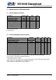
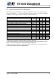
3.4 Analog Characteristics of Regulators
Parameter Symbol Min Typ Max Unit
IOVDD
Recommended voltage setting range 1.7 3.6 V
Voltage setting step size 50 60 70 mV
Default setting, reset mode
1
1.8 V
Default setting, active mode
2
1.8 / 3.3
3
V
Load regulation 4.0 mV/mA
Line regulation from VHIGH 2.0 mV/V
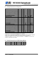
Continuous current 30
4
40 mA
CVDD
Recommended voltage setting range 1.8 2.6 V
Voltage setting step size 35 48 55 mV
Default setting, reset mode
1
1.8 V
Default setting, active mode
2
2.2 V
Continuous current 30
4
35 mA
Load regulation 2.0 mV/mA
Line regulation from VHIGH 2.0 mV/V
AVDD
Recommended voltage setting range 2.6 3.6 V
Voltage setting step size 35 46 55 mV
Default setting, reset mode
1
2.5 V
Default setting, active mode
2
2.7 V
Continuous current 30
4
70 mA
Load regulation 1.5 mV/mA
Line regulation from VHIGH 2.0 mV/V
1
Device enters reset mode when XRESET pin is pulled low.
2
Device enters active mode when XRESET pin is pulled high after reset mode. Regulator
settings can be modified when booted from external memory (see Section 7).
3
Depends on GPIO0_7 pin status in boot (see Section 7). VS1000b/c used 1.8V / 3.6V.
4
Device is tested with a 30 mA load.
3.5 Analog Characteristics of VHIGH Voltage Monitor
Parameter Symbol Min Typ Max Unit
Trigger voltage AMON 1.07×AVDD V
Hysteresis 50 mV
Version: 1.5, 2016-06-09 7