
User Manual


MCP2551
DS21667F-page 12 © 2010 Microchip Technology Inc.
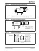
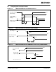
2.3 AC Characteristics
AC Specifications
Electrical Characteristics:
Industrial (I): TAMB = -40°C to +85°C VDD = 4.5V to 5.5V
Extended (E): T
AMB = -40°C to +125°C VDD = 4.5V to 5.5V
Param
No.
Sym Characteristic Min Max Units Conditions
1t
BIT Bit time 1 62.5 µs VRS = 0V
2fBIT Bit frequency 16 1000 kHz VRS = 0V
3 TtxL2bus(d) Delay TXD to bus active — 70 ns
-40°C ≤ TAMB ≤ +125°C,
V
RS = 0V
4 TtxH2bus(r) Delay TXD to bus inactive
— 125 ns
-40°C ≤ TAMB ≤ +85°C,
V
RS = 0V
— 170 ns
-40°C ≤ T
AMB ≤ +125°C,
V
RS = 0V
5 TtxL2rx(d) Delay TXD to receive active
— 130 ns
-40°C ≤ TAMB ≤ +125°C,
V
RS = 0V
— 250 ns
-40°C ≤ T
AMB ≤ +125°C,
R
S = 47 kΩ
6 TtxH2rx(r)
Delay TXD to receiver
inactive
— 175 ns
-40°C ≤ T
AMB ≤ +85°C,
V
RS = 0V
— 225 ns
-40°C ≤ TAMB ≤ +85°C,
R
S = 47 kΩ
— 235 ns
-40°C ≤ TAMB ≤ +125°C,
V
RS = 0V
— 400 ns
-40°C ≤ T
AMB ≤ +125°C,
R
S = 47 kΩ
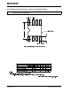
7 SR CANH, CANL slew rate 5.5 8.5 V/µs
Refer to Figure 2-1;
R
S = 47 kΩ, (Note 1)
10 t
WAKE
Wake-up time from standby
(Rs pin)
—5µsSee Figure 2-5
11 TbusD2rx(s)
Bus Dominant to RXD Low
(Standby mode)
— 550 ns V
RS = +4V; (See Figure 2-6)
12
C
IN(CANH)
C
IN(CANL)
CANH; CANL input
capacitance
—
20
(typical)
pF
1 Mb/s data rate;
VTXD = VDD, (Note 1)
13 C
DIFF
Differential input
capacitance
—
10
(typical)
pF
1 Mb/s data rate
(Note 1)
14 TtxL2busZ
TX Permanent Dominant
Timer Disable Time
1.25 4 ms
15 TtxR2pdt(res)
TX Permanent Dominant
Timer Reset Time
—1µs
Rising edge on TXD while
device is in permanent
Dominant state
Note 1: This parameter is periodically sampled and not 100% tested.