
MCP73831T Datasheet


© 2008 Microchip Technology Inc. DS21984E-page 13
MCP73831/2
4.0 DEVICE OVERVIEW
The MCP73831/2 are highly advanced linear charge
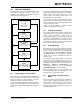
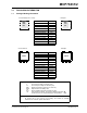
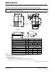
management controllers. Figure 4-1 depicts the
operational flow algorithm from charge initiation to
completion and automatic recharge.
FIGURE 4-1: Flowchart.
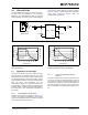
4.1 Undervoltage Lockout (UVLO)
An internal UVLO circuit monitors the input voltage and
keeps the charger in Shutdown mode until the input
supply rises above the UVLO threshold. The UVLO
circuitry has a built in hysteresis of 100 mV.
In the event a battery is present when the input power
is applied, the input supply must rise 150 mV above the
battery voltage before the MCP73831/2 becomes oper-
ational.
The UVLO circuit places the device in Shutdown mode
if the input supply falls to within +50 mV of the battery
voltage. Again, the input supply must rise to a level
150 mV above the battery voltage before the
MCP73831/2 become operational.
The UVLO circuit is always active. Whenever the input
supply is below the UVLO threshold or within +50 mV
of the voltage at the V
BAT
pin, the MCP73831/2 are
placed in a Shutdown mode.
During any UVLO condition, the battery reverse
discharge current will be less than 2 µA.
4.2 Charge Qualification
For a charge cycle to begin, all UVLO conditions must
be met and a battery or output load must be present. A
charge current programming resistor must be
connected from PROG to V
SS
. If the PROG pin is open
or floating, the MCP73831/2 are disabled and the
battery reverse discharge current is less than 2 µA. In
this manner, the PROG pin acts as a charge enable
and can be used as a manual shutdown.
4.3 Preconditioning
If the voltage at the V
BAT
pin is less than the precondi-
tioning threshold, the MCP73831/2 enter a precondi-
tioning or Trickle Charge mode. The preconditioning
threshold is factory set. Refer to Section 1.0 “Electri-
cal Characteristics” for preconditioning threshold
options and the Product Identification System for
standard options.
In this mode, the MCP73831/2 supply a percentage of
the charge current (established with the value of the
resistor connected to the PROG pin) to the battery. The
percentage or ratio of the current is factory set. Refer to
Section 1.0 “Electrical Characteristics” for
preconditioning current options and the ”Product
Identification System” for standard options.
When the voltage at the V
BAT
pin rises above the
preconditioning threshold, the MCP73831/2 enter the
Constant-Current or Fast Charge mode.
4.4 Fast Charge Constant-Current
Mode
During the Constant-Current mode, the programmed
charge current is supplied to the battery or load. The
charge current is established using a single resistor
from PROG to V
SS
. Constant-Current mode is
maintained until the voltage at the V
BAT
pin reaches the
regulation voltage, V
REG
.
SHUTDOWN MODE
V
DD
< V
UVLO
V
DD
< V
BAT
or
PROG > 200 kΩ
STAT = Hi-Z
PRECONDITIONING
MODE
Charge Current = I
PREG
STAT = LOW
FAST CHARGE
MODE
Charge Current = I
REG
STAT = LOW
CONSTANT VOLTAGE
MODE
Charge Voltage = V
REG
STAT = LOW
V
BAT
< V
PTH
V
BAT
> V
PTH
V
BAT
= V
REG
V
BAT
< V
RTH
V
BAT
> V
PTH
I
BAT
< I
TERM
CHARGE COMPLETE
MODE
No Charge Current
STAT = HIGH (MCP73831)
STAT = Hi-Z (MCP73832)