
Datasheet


E-mail:sales@hoperf.com
Rev1.0
RFM
95CW
www.hoperf.com
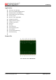
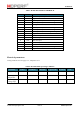
Table1. Module Pin Definition of RFM95CW
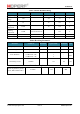
Electrical parameters
Testing conditions: Power supply 3.3V, temperature 25℃
Table2. Recommended Operating Conditions
Parameter Symbol Conditions Minimum Typical Value
Maximum
Unit
Supply Voltage
VDD 1.8 3.3 3.7 V
Operating
Temperature
T -40 85 ℃
Power Supply
Voltage Slope
1 mV/us
Pin No.
Pin Name Description
1 ANT Antenna Input &Output
2 GND Digital Ground
3 DIO3 Data Input & Output, Software Configuration
4 DIO4 Data Input & Output, Software Configuration
5 3.3V Voltage 3.3V
6 DIO0 Data Input & Output, Software Configuration
7 DIO1 Data Input & Output, Software Configuration
8 DIO2 Data Input & Output,Receiving Data Output
9 GND Digital Ground
10 MISO SPI Data Output
11 MOSI SPI Data Input
12 SCK SPI clock Input
13 NSS SPI slave Input
14 RESET Reset, Active Low
15 DIO5 Data Input & Output, Software Configuration
16 GND Digital Ground