
Datasheet
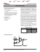
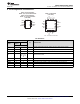
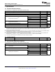
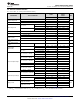

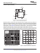
Table Of Contents
- 1 Features
- 2 Applications
- 3 Description
- 4 Simplified Schematic
- Table of Contents
- 5 Revision History
- 6 Pin Configuration and Functions
- 7 Specifications
- 8 Detailed Description
- 9 Applications and Implementation
- 10 Power Supply Recommendations
- 11 Device and Documentation Support
- 12 Mechanical, Packaging, and Orderable Information

NA555
,
NE555
,
SA555
,
SE555
SLFS022I –SEPTEMBER 1973–REVISED SEPTEMBER 2014
www.ti.com
7.5 Operating Characteristics
V
CC
= 5 V to 15 V, T
A
= 25°C (unless otherwise noted)
NA555
SE555 NE555
TEST
PARAMETER UNIT
SA555
CONDITIONS
(1)
MIN TYP MAX MIN TYP MAX
Each timer, monostable
(3)
T
A
= 25°C 0.5 1.5
(4)
1 3
Initial error of timing
%
interval
(2)
Each timer, astable
(5)
1.5 2.25
Each timer, monostable
(3)
T
A
= MIN to MAX 30 100
(4)
50
Temperature coefficient of ppm/
timing interval °C
Each timer, astable
(5)
90 150
Each timer, monostable
(3)
T
A
= 25°C 0.05 0.2
(4)
0.1 0.5
Supply-voltage sensitivity of
%/V
timing interval
Each timer, astable
(5)
0.15 0.3
C
L
= 15 pF,
Output-pulse rise time 100 200
(4)
100 300 ns
T
A
= 25°C
C
L
= 15 pF,
Output-pulse fall time 100 200
(4)
100 300 ns
T
A
= 25°C
(1) For conditions shown as MIN or MAX, use the appropriate value specified under recommended operating conditions.
(2) Timing interval error is defined as the difference between the measured value and the average value of a random sample from each
process run.
(3) Values specified are for a device in a monostable circuit similar to Figure 9, with the following component values: R
A
= 2 kΩ to 100 kΩ,
C = 0.1 μF.
(4) On products compliant to MIL-PRF-38535, this parameter is not production tested.
(5) Values specified are for a device in an astable circuit similar to Figure 12, with the following component values: R
A
= 1 kΩ to 100 kΩ,
C = 0.1 μF.
6 Submit Documentation Feedback Copyright © 1973–2014, Texas Instruments Incorporated
Product Folder Links: NA555 NE555 SA555 SE555