
Datasheet
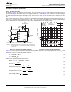

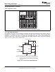
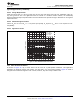
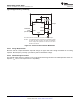


Table Of Contents
- 1 Features
- 2 Applications
- 3 Description
- 4 Simplified Schematic
- Table of Contents
- 5 Revision History
- 6 Pin Configuration and Functions
- 7 Specifications
- 8 Detailed Description
- 9 Applications and Implementation
- 10 Power Supply Recommendations
- 11 Device and Documentation Support
- 12 Mechanical, Packaging, and Orderable Information

S
V
CC
RESET V
CC
OUT
DISCH
GND
CONT
TRIG
4 8
3
7
6
1
5
2
THRES
R
C
C
C
0.01
C
C
= 14.7 µF
R
C
= 100 kΩ
Output C
RESET V
CC
OUT
DISCH
GND
CONT
TRIG
4 8
3
7
6
1
5
2
THRES
R
B
33 kΩ
0.001
0.01
µF
C
B
= 4.7 µF
R
B
= 100 kΩ
Output BOutput A
R
A
= 100 kΩ
C
A
= 10 µF
µF
0.01
µF
0.001
33 kΩ
RA
THRES
2
5
1
6
7
3
84
TRIG
CONT
GND
DISCH
OUT
V
CC
RESET
µF
µF
C
B
C
A
Pin numbers shown are for the D, JG, P, PS, and PW packages.
NOTE A: S closes momentarily at t = 0.
Voltage − 2 V/div
ÎÎÎÎÎ
ÎÎÎÎÎ
ÎÎÎÎÎ
ÎÎÎÎÎ
ÎÎÎÎÎ
R
A
= 3 kΩ
R
B
= 500 Ω
R
L
= 1 kΩ
See Figure 20
ÎÎÎÎÎÎ
ÎÎÎÎÎÎ
ÎÎÎÎÎÎ
ÎÎÎÎÎÎ
Capacitor Voltage
ÎÎÎÎÎ
ÎÎÎÎÎ
ÎÎÎÎÎ
ÎÎÎÎÎ
Output Voltage
ÎÎÎÎÎÎÎ
ÎÎÎÎÎÎÎ
ÎÎÎÎÎÎÎ
ÎÎÎÎÎÎÎ
Modulation Input Voltage
Time − 0.1 ms/div
NA555
,
NE555
,
SA555
,
SE555
www.ti.com
SLFS022I –SEPTEMBER 1973–REVISED SEPTEMBER 2014
Typical Applications (continued)
9.2.3.3 Application Curves
Figure 21. Pulse-Position-Modulation Waveforms
9.2.4 Sequential Timer
Many applications, such as computers, require signals for initializing conditions during start-up. Other
applications, such as test equipment, require activation of test signals in sequence. These timing circuits can be
connected to provide such sequential control. The timers can be used in various combinations of astable or
monostable circuit connections, with or without modulation, for extremely flexible waveform control. Figure 22
shows a sequencer circuit with possible applications in many systems, and Figure 23 shows the output
waveforms.
Figure 22. Sequential Timer Circuit
Copyright © 1973–2014, Texas Instruments Incorporated Submit Documentation Feedback 17
Product Folder Links: NA555 NE555 SA555 SE555