
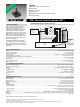
Data Sheet

Specifi cations are subject to change without notice.
The device characteristics and parameters in this data sheet can and do vary in different applications and actual device performance may vary over time.
Users should verify actual device performance in their specifi c applications.
EAW - Absolute Contacting Encoder (ACE
™
)
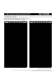
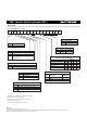
Dimensional Drawings
Panel Hole Dimensions
Shaft Style
C
"D"
Shaft Style RShaft Style B
"D" DIMENSION EXTENDS FROM SHAFT END TO BUSHING FACE
"D" = (SHAFT LENGTH, FMS) – (BUSHING LENGTH)
PCB Board Hole Pattern w/PCB Bracket
6.00 ± 0.05
(.236 ± .002)
1.6
(.063)
1.19
(.047)
6.32 + 0.03/– 0.06
(.249 + .001/– .003)
DIA.
5.54 ± .076
(.218 ± .003)
6.32 + 0.03/– 0.06
(.249 + .001/– .003)
DIA.
1.6
(.063)
1.19
(.047)
9.5
(.375)
9.93
(.391)
3.17
(.125)
DIA.
DIA.
2.54
(.100)
25.4
(1.00)
1.2
(.047)
TYP.
DIA. 10 PLCS.
DIA.
TOLERANCES EXCEPT WHERE NOTED:
.XX = ± .XXX = ±
DIMENSIONS:
.51
(.02)
.127
(.005)
MM
(IN)
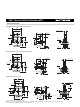
Bushing Mounted: Housing A with Rear Facing Terminals
Panel Hole Dimensions PCB Board Hole Pattern w/PCB Bracket
9.5
(.375)
9.93
(.391)
3.17
(.125)
DIA.
DIA.
2.54
(.100)
25.4
(1.00)
15.24
(.600)
5.08
(.200)
1.2
(.047)
TYP.
11.43
(.450)
2 PLCS.
DIA. 14 PLCS.
2 PLCS.
PCB Bracket Mounted: Housing B
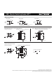
PCB Board Hole Pattern w/PCB Bracket
9.5
(.375)
9.93
(.391)
3.17
(.125)
DIA.
DIA.
2.54
(.100)
25.4
(1.00)
1.2
(.047)
TYP.
DIA. 10 PLCS.
Bushing Mounted: Housing A with Forward Facing Terminals