
Datasheet


DG600F Coin Acceptor Technical Manual Version 1.0 - 06.2010
Page 12 of 21-
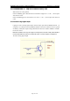
6. Dip Switch Functions Setting
◎Dip Switch funcitons
SW1
Port Level
SW2
Security
SW3
Transmitting
SW4
Inhibiting
ON
NC
Special
RS232
< +1V
OFF
NO
Normal
Pulse
> +3V
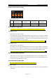
6.1
6.16.1
6.1
Serial Port Output Level
Serial Port Output LevelSerial Port Output Level
Serial Port Output Level
Note: The two mode options as blow are not suitable for parallel port output mode.
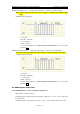
6.1.1 Mode 1—N.O.
When SW1 is on “OFF” position,
On standby, coin receiving output NPN transistor is open collector; on acceptance of enough
coins ( no less than machine charge amount), NPN transistor is turned on to short circuit for a
period of 25ms/45ms/65ms/100ms (+/-20%).here output voltage should be less than 0.7V and
max 100mA is available for electric current.
Note: it can set the period of 25ms/45ms/65ms/100ms in coin acceptor parameter A2.
6.1.2 Mode 2—N.C.
When SW1 is on “ON” position,
On standby, coin receiving output NPN transistor is short circuit, max 100mA is available for
electric current; on acceptance of enough coins ( no less than machine charge amount), NPN
transistor is turned on to open circuit for a period of 25ms/45ms/65ms/100ms (+/-20%).
Note: It can set the period of 25ms/45ms/65ms/100ms in coin acceptor parameter A2.
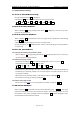
6.2
6.26.2
6.2
Coin
Coin Coin
Coin I
II
Identification
dentificationdentification
dentification Security
Security Security
Security
When SW2 is on "OFF" position, it means the high security of coin acceptor identifies coins.
When SW2 is on "ON" position, it means the low security of coin acceptor identifies coins,
acceptor can accept some defected coins.
6.3
6.36.3
6.3
Serial Output Signal Format
Serial Output Signal FormatSerial Output Signal Format
Serial Output Signal Format
Note: This option is not suitable for parallel port output mode.
6.3.1 Pulse Signal
When SW3 in on "OFF "position, on acceptance of enough valid coins, Serial port sends out
pulse signal.