DG600F Coin Acceptor Technical Manual Version 1.0 - 06.
DG600F Coin Acceptor Technical Manual Version 1.0 - 06.2010 Index 1. .Alter Log ....................................................................................................................................4 2. Introduction.................................................................................................................................4 2.1 Main Features:.............................................................................................................4 2.2 Specification:...
DG600F Coin Acceptor Technical Manual Version 1.0 - 06.2010 8.6 Serial Port RS232 Signal Output Format A4 .....................................................19 8.7 Serial Or Parallel Port Option A5.......................................................................19 8.8 Exit The Setting.........................................................................................................19 9. Common Faulties ..........................................................................................
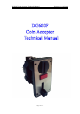
DG600F Coin Acceptor Technical Manual Version 1.0 - 06.2010 1. .Alter Log Date/Author 2010/06 DG Simple Introduction Basic functions are completed。 Version 1.0 2. Introduction DG600F Series of coin acceptor is a electronic coin acceptor with high reliability, Which is widely used in amusement facilities, vending machines and so on. 2.1 Main Features: Features: Enable to recognize 6 groups of coins in different denomination.
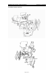
DG600F Coin Acceptor Technical Manual 3. Product Structure and Size Page 5 of 21- Version 1.0 - 06.
DG600F Coin Acceptor Technical Manual Page 6 of 21- Version 1.0 - 06.
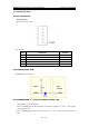
DG600F Coin Acceptor Technical Manual Version 1.0 - 06.2010 4. Serial Output Mode 4.1 Ports Instruction Serial connector Special connector:5Pin ◎Serial Port PIN FUNCTION 1 +12V 2 Serial Signal Output 3 0V 4 Counter Output 5 Inhibiting port(refer to item 4.2) ACTIVE Low 4.2 Forbid Accepting Coins ◎Inhibiting port connection 4.2.
DG600F Coin Acceptor Technical Manual Version 1.0 - 06.2010 4.2.2 Forbidden Mode 2 — High Level forbid accepting coins When SW4 is on “ON” position, If the 5th Inhibiting port is disconnected or connected to a high level(>+3V), coin acceptor will refuse all coins。 If the 5th Inhibiting port is disconnected or connected to a high level(<+1V), coin acceptor will accept all coins。 4.
DG600F Coin Acceptor Technical Manual Version 1.0 - 06.2010 4.4 Counter Output ◎Counter Output Counter output consists of a open-collector NPN transistor , on acceptance of enough coins ( no less than machine charge amount), NPN transistor is turned on to short circuit for a period of 25ms/45ms/65ms/100ms (+/-20%).here output voltage should be less than 0.7V and max 200mA is available for electric current.
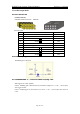
DG600F Coin Acceptor Technical Manual Version 1.0 - 06.2010 5. Parallel Output Mode 5.1 Ports Instruction Parallel connector Industrial standard connector:10Pin DIL ◎Parallel ports PIN FUNCTION ACTIVE 1 0V 2 +12V 3 Accept C5 Low 4 Accept C6 Low 5 None 6 Inhibiting port(refer to item 5.2) 7 Accept C1 Low 8 Accept C2 Low 9 Accept C3 Low 10 Accept C4 Low 5.2 Forbid Accepting coins ◎Inhibiting port connection 5.2.
DG600F Coin Acceptor Technical Manual Version 1.0 - 06.2010 5.2.2 Forbidden Mode 2 — High Level forbid accepting coins When SW4 is on “ON” position If the 6th Inhibiting port is disconnected or connected to a high level(>+3V), coin acceptor will refuse all coins. If the 6th Inhibiting port is connected to a low level(<+1V), coin acceptor will refuse all coins. 5.
DG600F Coin Acceptor Technical Manual Version 1.0 - 06.2010 6. Dip Switch Functions Setting ◎Dip Switch funcitons SW1 Port Level SW2 Security SW3 Transmitting SW4 Inhibiting NC Special RS232 < +1V NO Normal Pulse > +3V ON OFF 6.1 Serial Port Output Level Note: The two mode options as blow are not suitable for parallel port output mode. 6.1.1 Mode 1—N.O.
DG600F Coin Acceptor Technical Manual 6.3.1.1 Select mode 1-N.O.,In serial port output mode. ◎N.O. Pulse output oscillogram Version 1.0 - 06.2010 (SW1 is on "OFF" position) t1:Pulse duration of (25ms/45ms/65ms/100ms) The duration is set in coin acceptor parameters A2. t2:Pulse interval of 100ms 6.3.1.2 Select mode 2-N.C., In serial port output mode. (SW1 is on "ON" position) ◎N.C. Pulse output oscillogram t1:Pulse duration of (25ms/45ms/65ms/100ms) The duration is set in coin acceptor parametersA2.
DG600F Coin Acceptor Technical Manual Version 1.0 - 06.2010 6.3.2.1 Select mode 1-N.O., In serial port output mode. (SW1 is on "OFF" position) Note: Please select this mode when coin acceptor is connecting to machine's single port. ◎RS232 output oscillogram S:Start bit B0 to B7:8 data bits C:Even check STOP:Stop bit It can set the transmit rate(1200bps/2400bps/4800bps/9600bps)in coin acceptor parameter A2. 6.3.2.2 Select mode 2-N.C., In serial port output mode.
DG600F Coin Acceptor Technical Manual Version 1.0 - 06.2010 6.4.2 Forbidden Mode 2--High Level forbid accepting coins When SW4 is on “ON” position, If Inhibiting port is disconnected or connected to a high level(>+3V), coin acceptor will refuse all coins. If Inhibiting port is connected to a low level(<+1V),coin acceptor will accept all coins.
DG600F Coin Acceptor Technical Manual Version 1.0 - 06.2010 7. Coin Parameters Setting 7.1 Access To Coin Parameters Setting Keep pressing button A till CP is displayed. LED displays CP , press button A to select one of six groups of coins. CP C1 C2 C3 C4 C5 C6 7.2 Clean Up All Coin Parameters When it displays CP , keep pressing button B till CC is displayed, it will clean up all six groups of coin parameters . 7.
DG600F Coin Acceptor Technical Manual Version 1.0 - 06.2010 7.6 Exit Coin Parameters Setting After finish coins parameter setting, keep pressing button A for 2 seconds, release after it displays 88.
DG600F Coin Acceptor Technical Manual Version 1.0 - 06.2010 8. Coin Acceptor Parameters Setting 8.1 Acess To Coin Acceptor Parameters Setting Keep pressing button B buton till AP is displayed, it enters into setting mode. LED displays AP , press button A to select working parameters. AP A1 A2 A3 A4 8.2 Recover Coin Acceptor Parameters To The Defaulted Value Keep pressing B button when it displays AP , and release after “CC” is displayed, then all parameters is recover to the defaulted value.
DG600F Coin Acceptor Technical Manual Version 1.0 - 06.2010 8.5 Faulty Alarm Option A3 When it displays A3, press button B to display existing parameters stored in machine. 00 (Alarm doesn't ring) 01 (Alarm rings one time) 02 (Alarm keeps ringing) Press button B to adjust the needed parameter, press button A to next group of coin acceptor parametersA4. 8.
DG600F Coin Acceptor Technical Manual Version 1.0 - 06.2010 9. Common Faulties 9.1 Error Code(E1 Code(E1 - E7,EE) Error code E1 It displays E1 after power on, it means that the first pair of sensor is out of order. It displays E1 after deposit coin, it means that coin duration at the first pair of sensor is too long. Error code E2 It displays E2 after power on, it means that the first pair of sensor is out of order.
DG600F Coin Acceptor Technical Manual Version 1.0 - 06.2010 9.3 Send No Signal After Deposit Coins Coins Check if the machine charge amount setting is right or not, if coin value deposited falls short of the charge amount, Coin Acceptor would not send any signal. For instance, coin value deposited is 01, but machine charge amount is set as 02, then it would not send signal when only one coin is deposited, but send signals after deposit two coins. Please refer to 8.