
Calibration Guide


OPERATION MANUAL OF COIN ACCEPTOR ( Multi-coins Mode )
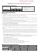
◆ITEM AND SPECIFICATION OF PRODUCT:
ITEM
SPECIFICATION
C315 C400 C500 C520
Available groups 3 4 5 5
Available coins per group 15 12 10 24
REMARK:
1. Standard output is pulse signal.
2. Item NO. with “B”, it means output signal
is byte. E.g. C315B.
3. Item NO. with “K”, it means the product
added control line function. E.g. C315K.
◆SETTING INSTRUCTION OF PRODUCT:
1. Set coin parameter
1) Turn the SENSITIVE SWITCH to stir to the “NOM” position, then turn the SETTING SWITCH to stir to the “SET” position. LED displays “00”.
2) Adjust the coin value in turn and let the LED display the value (01~A0;A0=100) which you need.
3) Deposit the coins in turn. If you program coins less than the available capacity , can add and store later.
4) If need to set up the other value group’s coin after set up, then re-programming step 2 and step 3.If need exit, set up the SETTING SWITCH to
the “START” position, then can use it.
5) When need to cancel all of the programmed coins ,after finish step 1, LED display “00” ,then keep press the COIN VALUE ADJUSTION
SWITCH, you will hear a “BI” sound after 2 seconds and LED will display “C” ,this moment is ok .
6) If need to cancel one of the different value groups, finish step 1 and step 2, keep press the COIN VALUE ADJUSTION SWITCH, you will be
hear a “BI” sound and LED will display “C”, this moment is ok.
2. Set signal output unit (i.e. how much for outputting one signal)
1) Turn the SENSITIVE SWITCH to stir to the “MGN” position, and then turn the SETTING SWITCH to stir to the “SET” position. LED display
“1”. Adjust the value in turn and let the LED display the value that you need (1~A0; A0=100). After this turn the SETTING SWITCH to stir to the
“START” position, and the SENSITIVE SWITCH to “NOM”, here you can go to the next step for coin parameter setting. If user don’t set, it
default to “1”.
2) If need re-set, do same as above. Turn the SENSITIVE SWITCH to stir to the “MGN” position, then turn the SETTING SWITCH to stir to the
“SET” position. Here LED display the value set before. If you need set bigger value than before, just directly press the COIN VALUE
ADJUSTION SWITCH to add up; If you need set smaller value than before, keep pressing the COIN VALUE ADJUSTION SWITCH until
heard a “BI” tone after 2 seconds, and LCD displays “1”, then press COIN VALUE ADJUSTION SWITCH to make LED display the value you
need.
E.g..: Coin parameter ($0.1 set as “1”; $0.5 set as “5”; $1.0 set as “10”)
1)The signsl output unit as default value “1”: When insert a coin, then LED will display coin parameter. E.g. When insert a $0.5 coin,
LED will display “5”. Pulse outputting means output five pulse signals. Byte outputting means output signal is “Ox05”.
2)Set the signal output unit as “10”
When insert a coin of $1.0, coin acceptor output one signal
When insert two coins of $0.5, coin acceptor output one signal
When insert coins of $0.5+$0.1+$0.1+$0.1+$0.1+$0.1, coin acceptor output one signal
When inset coins of $0.1+$0.1+$0.1+$0.1+$0.1+$0.1+$0.1+$0.1+$0.1+$0.1, coin acceptor output one signal.
(if only the amount of coins’ value is equal to “10”, coin acceptor will output one signal)
◆STANDARDS AND OPERATIONG INSTRUCTION:
Apply to coin’s diameter Apply to coin thickness Work voltage Temperature
18mm ~ 29mm 1.2mm ~ 3.0mm
DC 12V±20%
-10˚C ~ 45˚C
Switch Instruction:
N.O./N.C. FAST/MED/SLOW START/SET MGN/NOM/MAX TACT SWITCH
N.O./N.C. Switch Signal speed switch Setting switch Sensitive switch Coin value adjustion switch
Connecting instructions of connector:
Generated by Foxit PDF Creator © Foxit Software
http://www.foxitsoftware.com For evaluation only.