
Data Sheet
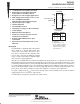
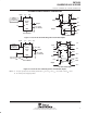
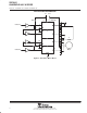

SN754410
QUADRUPLE HALF-H DRIVER
SLRS007B – NOVEMBER 1986 – REVISED NOVEMBER 1995
3
POST OFFICE BOX 655303 • DALLAS, TEXAS 75265
POST OFFICE BOX 1443
• HOUSTON, TEXAS 77251–1443
absolute maximum ratings over operating free-air temperature range (unless otherwise noted)
†
Output supply voltage range, V
CC1
(see Note 1) –0.5 V to 36 V. . . . . . . . . . . . . . . . . . . . . . . . . . . . . . . . . . . . . .
Output supply voltage range, V
CC2
–0.5 V to 36 V. . . . . . . . . . . . . . . . . . . . . . . . . . . . . . . . . . . . . . . . . . . . . . . . . .
Input voltage, V
I
36 V. . . . . . . . . . . . . . . . . . . . . . . . . . . . . . . . . . . . . . . . . . . . . . . . . . . . . . . . . . . . . . . . . . . . . . . . . .
Output voltage range, V
O
–3 V to V
CC2
+ 3 V. . . . . . . . . . . . . . . . . . . . . . . . . . . . . . . . . . . . . . . . . . . . . . . . . . . . .
Peak output current (nonrepetitive, t
w
≤5 ms) ±2 A. . . . . . . . . . . . . . . . . . . . . . . . . . . . . . . . . . . . . . . . . . . . . . . . .
Continuous output current, I
O
±1.1 A. . . . . . . . . . . . . . . . . . . . . . . . . . . . . . . . . . . . . . . . . . . . . . . . . . . . . . . . . . . . . .
Continuous total power dissipation at (or below) 25°C free-air temperature (see Note 2) 2075 mW. . . . . . . .
Operating free-air temperature range, T
A
–40°C to 85°C. . . . . . . . . . . . . . . . . . . . . . . . . . . . . . . . . . . . . . . . . . . .
Operating virtual junction temperature range, T
J
–40°C to 150°C. . . . . . . . . . . . . . . . . . . . . . . . . . . . . . . . . . . .
Storage temperature range, T
stg
–65°C to 150°C. . . . . . . . . . . . . . . . . . . . . . . . . . . . . . . . . . . . . . . . . . . . . . . . . .
Lead temperature 1,6 mm (1/16 inch) from case for 10 seconds 260°C. . . . . . . . . . . . . . . . . . . . . . . . . . . . . . .
†
Stresses beyond those listed under “absolute maximum ratings” may cause permanent damage to the device. These are stress ratings only, and
functional operation of the device at these or any other conditions beyond those indicated under “recommended operating conditions” is not
implied. Exposure to absolute-maximum-rated conditions for extended periods may affect device reliability.
NOTES: 1. All voltage values are with respect to network GND.
2. For operation above 25°C free-air temperature, derate linearly at the rate of 16.6 mW/°C. To avoid exceeding the design maximum
virtual junction temperature, these ratings should not be exceeded. Due to variations in individual device electrical characteristics
and thermal resistance, the built-in thermal overload protection can be activated at power levels slightly above or below the rated
dissipation.
recommended operating conditions
MIN MAX UNIT
Output supply voltage, V
CC1
4.5 5.5 V
Output supply voltage, V
CC2
4.5 36 V
High-level input voltage, V
IH
2 5.5 V
Low-level input voltage, V
IL
–0.3
‡
0.8 V
Operating virtual junction temperature, T
J
–40 125 °C
Operating free-air temperature, T
A
–40 85 °C
‡
The algebraic convention, in which the least positive (most negative) limit is designated as minimum, is used in this data sheet for logic voltage
levels.