
Data Sheet

L7800 SERIES
15/34
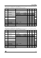
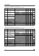
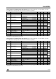
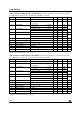
Table 23: Electrical Characteristics Of L7824C (refer to the test circuits, T
J
= 0 to 125°C, V
I
= 33V,
I
O
= 500 mA, C
I
= 0.33 µF, C
O
= 0.1 µF unless otherwise specified).
(*) Load and line regulation are specified at constant junction temperature. Changes in V
O
due to heating effects must be taken into account
separately. Pulse testing with low duty cycle is used.
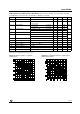
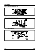
Figure 8: Dropout Voltage vs Junction
Temperature
Figure 9: Peak Output Current vs Input/output
Differential Voltage
Symbol Parameter Test Conditions Min. Typ. Max. Unit
V
O
Output Voltage T
J
= 25°C 232425 V
V
O
Output Voltage I
O
= 5 mA to 1 A P
O
≤ 15W
V
I
= 27 to 38 V
22.8 24 25.2 V
∆V
O
(*) Line Regulation V
I
= 27 to 38 V T
J
= 25°C 480 mV
V
I
= 30 to 36 V T
J
= 25°C 240
∆V
O
(*) Load Regulation I
O
= 5 mA to 1.5 A T
J
= 25°C 480 mV
I
O
= 250 to 750 mA T
J
= 25°C 240
I
d
Quiescent Current T
J
= 25°C 8 mA
∆I
d
Quiescent Current Change I
O
= 5 mA to 1 A 0.5 mA
V
I
= 27 to 38 V 1
∆V
O
/∆T Output Voltage Drift I
O
= 5 mA -1.5 mV/°C
eN Output Noise Voltage B =10Hz to 100KHz T
J
= 25°C 170 µV/V
O
SVR Supply Voltage Rejection V
I
= 28 to 38 V f = 120Hz 50 dB
V
d
Dropout Voltage I
O
= 1 A T
J
= 25°C 2 V
R
O
Output Resistance f = 1 KHz 28 mΩ
I
sc
Short Circuit Current V
I
= 35 V T
J
= 25°C 0.15 A
I
scp
Short Circuit Peak Current T
J
= 25°C 2.1 A