
Data Sheet
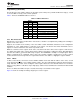

ChannelSelectionBits(Read/Write)
Channel1
Channel0
Channel2
Channel3
Channel4
Channel5
Channel6
Channel7
B7 B6 B5 B4 B3 B2 B1 B0
17
TCA9548A
www.ti.com
SCPS207F –MAY 2012–REVISED NOVEMBER 2016
Product Folder Links: TCA9548A
Submit Documentation FeedbackCopyright © 2012–2016, Texas Instruments Incorporated
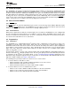
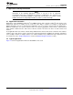
8.5.4 Control Register
Following the successful acknowledgment of the address byte, the bus master sends a command byte that is
stored in the control register in the TCA9548A (see Figure 12). This register can be written and read via the I
2
C
bus. Each bit in the command byte corresponds to a SCn/SDn channel and a high (or 1) selects this channel.
Multiple SCn/SDn channels may be selected at the same time. When a channel is selected, the channel
becomes active after a stop condition has been placed on the I
2
C bus. This ensures that all SCn/SDn lines are in
a high state when the channel is made active, so that no false conditions are generated at the time of
connection. A stop condition always must occur immediately after the acknowledge cycle. If multiple bytes are
received by the TCA9548A, it saves the last byte received.
Figure 12. Control Register
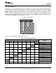
Table 2 shows the TCA9548A Command Byte Definition.
Table 2. Command Byte Definition
CONTROL REGISTER BITS
COMMAND
B7 B6 B5 B4 B3 B2 B1 B0
X X X X X X X
0 Channel 0 disabled
1 Channel 0 enabled
X X X X X X
0
X
Channel 1 disabled
1 Channel 1 enabled
X X X X X
0
X X
Channel 2 disabled
1 Channel 2 enabled
X X X X
0
X X X
Channel 3 disabled
1 Channel 3 enabled
X X X
0
X X X X
Channel 4 disabled
1 Channel 4 enabled
X X
0
X X X X X
Channel 5 disabled
1 Channel 5 enabled
X
0
X X X X X X
Channel 6 disabled
1 Channel 6 enabled
0
X X X X X X X
Channel 7 disabled
1 Channel 7 enabled
0 0 0 0 0 0 0 0
No channel selected, power-up/reset
default state