
Data Sheet


74HC_HCT4051 All information provided in this document is subject to legal disclaimers. © NXP Semiconductors N.V. 2016. All rights reserved.
Product data sheet Rev. 8 — 5 February 2016 19 of 31
NXP Semiconductors
74HC4051; 74HCT4051
8-channel analog multiplexer/demultiplexer
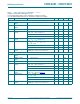
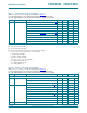
For 74HC4051: V
M
=0.5 V
CC
.
For 74HCT4051: V
M
=1.3V.
Fig 14. Turn-on and turn-off times
DDG
W
3/=
W
3+=
VZLWFK2))
VZLWFK21
VZLWFK21
9
RV
RXWSXW
9
RV
RXWSXW
(6QLQSXWV
9
0
9
,
9
W
3=/
W
3=+
Definitions for test circuit; see Table 11:
R
T
= termination resistance should be equal to the output impedance Z
o
of the pulse generator.
C
L
= load capacitance including jig and probe capacitance.
R
L
= load resistance.
S1 = Test selection switch.
Fig 15. Test circuit for measuring AC performance
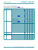
9
0
9
0
W
:
W
:
9
9
,
9
,
QHJDWLYH
SXOVH
SRVLWLYH
SXOVH
9
9
0
9
0
W
I
W
U
W
U
W
I
DDH
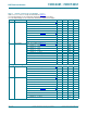
9
&&
9
&&
RSHQ
*1'
9
((
9
,
9
RV
'87
&
/
5
7
5
/
6
38/6(
*(1(5$725
9
LV