
SP3485 datasheet

10/15/02 SP3481/3485 Low Power Half-Duplex RS485 Transceivers © Copyright 2000 Sipex Corporation
6
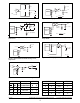
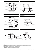
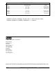
Figure 8. Driver Propagation Delay Waveforms
Figure 12. Receiver Enable and Disable Waveforms
Figure 11. Receiver Propagation Delay Waveforms
Figure 10. Driver Enable and Disable Timing Waveforms
0V
V
OH
tPLH
tPHL
V
OM
tPHL
tPLH
3V
V
OL
VOH
1.5V
1.5V
INPUT
Y OUTPUT
V
OM
Z OUTPUT
V
OL
V
OM
V
OM
V
OM
=
V
OH
+ V
OL
2
≈ 1.5V
0V
V
OH
t
PZH
0.25V
t
PHZ
V
OM
t
PZL
t
PLZ
3V
V
OL
V
CC
1.5V
1.5V
DE
OUTPUT
HIGH
V
OM
0.25V
0V
OUTPUT
LOW
V
OM
=
V
OH
+ V
OL
2
≈ 1.5V
3V
0V
V
CC
tRPLH
1.5V
t
RPHL
VOM
VOM
0V
1.5V
INPUT
OUTPUT
V
OM
=
V
CC
2
NOTE 1: The input pulse is supplied by a generator with the following characteristics:
PRR=250KHz, 50% duty cycle, t
r
< 6.0ns, Z
0
=50Ω.
NOTE 2: C
L
includes probe and stray capacitance.
IN
1.5V
t
DO1
1.5V
t
DO2
3V
0V
OUT
50%
50%
10%
10%
90%
90%
t
TD
t
TD
2.0V
-2.0V
Figure 9. Driver Differential Output Delay and Transition
Time Waveforms
3V
0V
t
PRHZ
1.5V
t
PRZH
tPRSH
1.5V
1.5V
10%
0V
V
OH
RE
OUTPUT
S1 is open
S2 is closed
S3 = 1.5V
3V
0V
t
PRLZ
1.5V
t
PRZL
t
PRSL
1.5V
1.5V
10%
V
CC
RE
OUTPUT
S1 is closed
S2 is open
S3 = -1.5V
V
OL