
Data Sheet

997
Atmel | SMART SAM D21 [DATASHEET]
Atmel-42181G–SAM-D21_Datasheet–09/2015
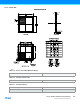
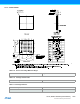
37. Packaging Information
37.1 Thermal Considerations
37.1.1 Thermal Resistance Data
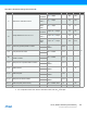
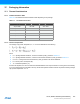
Table 37-1 summarizes the thermal resistance data depending on the package.
Table 37-1. Thermal Resistance Data
37.1.2 Junction Temperature
The average chip-junction temperature, T
J
, in °C can be obtained from the following:
where:
z θ
JA
= package thermal resistance, Junction-to-ambient (°C/W), provided in Table 37-1.
z θ
JC
= package thermal resistance, Junction-to-case thermal resistance (°C/W), provided in Table 37-1.
z θ
HEATSINK
= cooling device thermal resistance (°C/W), provided in the device datasheet.
z P
D
= device power consumption (W).
z T
A
= ambient temperature (°C).
From the first equation, the user can derive the estimated lifetime of the chip and decide if a cooling device is necessary
or not. If a cooling device is to be fitted on the chip, the second equation should be used to compute the resulting average
chip-junction temperature T
J
in °C.
Package Type θ
JA
θ
JC
32-pin TQFP 68 °C/W 25.8 °C/W
48-pin TQFP 78.8 °C/W 12.3 °C/W
64-pin TQFP 66.7 °C/W 11.9 °C/W
32-pin QFN 37.2 °C/W 15.0 °C/W
48-pin QFN 33 °C/W 11.4 °C/W
64-pin QFN 33.5 °C/W 11.2 °C/W