
Data Sheet

991
Atmel | SMART SAM D21 [DATASHEET]
Atmel-42181G–SAM-D21_Datasheet–09/2015
Notes: 1. These values are based on simulation. These values are not covered by test limits in production.
2. Cb = Capacitive load on each bus line. Otherwise noted, value of C
b
set to 20pF.
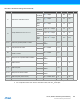
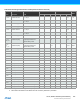
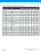
Table 36-61. I2C Interface Timing, Device Variant B
(1)
Symbol Parameter Conditions Min. Typ. Max. Units
t
R
Rise time for both SDA and SCL
Standard /
Fast Mode
I
C
b
(2)
= 400pF - 230 350
ns
Fast
Mode +
I
C
b
(2)
= 550pF 60 100
High
Speed
Mode
I
C
b
(2)
= 100pF 30 60
t
OF
Output fall time from V
IHmin
to V
ILmax
Standard /
Fast Mode
10pF < C
b
(2)
< 400pF 25 50
Fast
Mode +
10pF < C
b
(2)
< 550pF 20 30
High
Speed
Mode
10pF < C
b
(2)
< 100pF 10.0 20.0
t
HD;STA
Hold time (repeated) START condition
f
SCL
> 100kHz,
Master
t
LOW
-9 - -
t
LOW
Low period of SCL Clock f
SCL
> 100kHz 113 - -
t
BUF
Bus free time between a STOP and a
START condition
f
SCL
> 100kHz t
LOW
- -
t
SU;STA
Setup time for a repeated START condition
f
SCL
> 100kHz,
Master
t
LOW
+7 - -
t
HD;DAT
Data hold time
f
SCL
> 100kHz,
Master
9 - 12
t
SU;DAT
Data setup time
f
SCL
> 100kHz,
Master
104 - -
t
SU;STO
Setup time for STOP condition
f
SCL
> 100kHz,
Master
t
LOW
+9 - -
t
SU;DAT;rx
Data setup time (receive mode) f
SCL
> 100kHz, Slave 51 - 56
t
HD;DAT;tx
Data hold time (send mode) f
SCL
> 100kHz, Slave 71 90 138