
Data Sheet


92
Atmel | SMART SAM D21 [DATASHEET]
Atmel-42181G–SAM-D21_Datasheet–09/2015
When user makes a 32-bit access to offset 0x00, all registers are written but REGA, REGB, REGC can be updated at a
different time because of independent write synchronization
13.3.2.3 General read synchronization
Before any read of a core register, the user must check that the related bit in SYNCBUSY register is cleared.
Read access to core register is always immediate but the return value is reliable only if a synchonization of this core
register is not going.
13.3.2.4 Completion of synchronization
The user can either poll SYNCBUSY register or use the Synchronisation Ready interrupt (if available) to check when the
synchronization is complete.
13.3.2.5 Enable Write-Synchronization
Writing to the Enable bit in the Control register (CTRL.ENABLE) will also trigger write-synchronization and set
SYNCBUSY.ENABLE. CTRL.ENABLE will read its new value immediately after being written. The Synchronisation
Ready interrupt (if available) cannot be used for Enable write-synchronization.
13.3.2.6 Software Reset Write-Synchronization
Writing a one to the Software Reset bit in CTRL (CTRL.SWRST) will also trigger write-synchronization and set
SYNCBUSY.SWRST. When writing a one to the CTRL.SWRST bit it will immediately read as one. CTRL.SWRST and
SYNCBUSY.SWRST will be cleared by hardware when the peripheral has been reset. Writing a zero to the
CTRL.SWRST bit has no effect. The Synchronisation Ready interrupt (if available) cannot be used for Software Reset
write-synchronization.
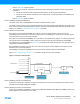
13.3.2.7 Synchronization Delay
The synchronization will delay the write or read access duration by a delay D, given by the equation:
Where is the period of the generic clock and is the period of the peripheral bus clock. A normal peripheral
bus register access duration is .
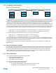
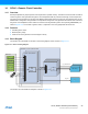
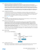
13.4 Enabling a Peripheral
To enable a peripheral clocked by a generic clock, the following parts of the system needs to be configured:
z A running clock source.
z A clock from the Generic Clock Generator must be configured to use one of the running clock sources, and the
generator must be enabled.
z The generic clock, through the Generic Clock Multiplexer, that connects to the peripheral needs to be configured
with a running clock from the Generic Clock Generator, and the generic clock must be enabled.
z The user interface of the peripheral needs to be unmasked in the PM. If this is not done the peripheral registers will
read as all 0’s and any writes to the peripheral will be discarded.
5 P
GCLK
⋅ 2 P
APB
⋅+ D 6 P
GCLK
⋅ 3 P
APB
⋅+<<
P
GCLK
P
APB
2 P
APB
⋅