
Data Sheet

887
Atmel | SMART SAM D21 [DATASHEET]
Atmel-42181G–SAM-D21_Datasheet–09/2015
33.5.10 Other Dependencies
Not applicable.
33.6 Functional Description
33.6.1 Principle of Operation
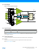
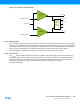
Each comparator has one positive input and one negative input. Each positive input may be chosen from a selection of
analog input pins. Each negative input may be chosen from a selection of analog input pins or internal inputs, such as a
bandgap reference voltage. The digital output from the comparator is one when the difference between the positive and
the negative input voltage is positive, and zero otherwise.
The individual comparators can be used independently (normal mode) or grouped in pairs to generate a window
comparison (window mode).
33.6.2 Basic Operation
33.6.2.1 Initialization
Before enabling the AC, the input and output events must be configured in the Event Control register (EVCTRL). These
settings cannot be changed while the AC is enabled.
Each individual comparator must also be configured by its respective Comparator Control register (COMPCTRL0) before
that comparator is enabled. These settings cannot be changed while the comparator is enabled.
z Select the desired measurement mode with COMPCTRLx.SINGLE. See “Starting a Comparison” on page
887 for more details
z Select the desired hysteresis with COMPCTRLx.HYST. See “Input Hysteresis” on page 891 for more details
z Select the comparator speed versus power with COMPCTRLx.SPEED. See “Propagation Delay vs. Power
Consumption” on page 891 for more details
z Select the interrupt source with COMPCTRLx.INTSEL
z Select the positive and negative input sources with the COMPCTRLx.MUXPOS and
COMPCTRLx.MUXNEG bits. See section “Selecting Comparator Inputs” on page 889 for more details
z Select the filtering option with COMPCTRLx.FLEN
33.6.2.2 Enabling, Disabling and Resetting
The AC is enabled by writing a one to the Enable bit in the Control A register (CTRLA.ENABLE). The individual
comparators must be also enabled by writing a one to the Enable bit in the Comparator x Control registers
(COMPCTRLx.ENABLE). The AC is disabled by writing a zero to CTRLA.ENABLE. This will also disable the individual
comparators, but will not clear their COMPCTRLx.ENABLE bits.
The AC is reset by writing a one to the Software Reset bit in the Control A register (CTRLA.SWRST). All registers in the
AC, except DEBUG, will be reset to their initial state, and the AC will be disabled. Refer to the CTRLA register for details.
33.6.2.3 Starting a Comparison
Each comparator channel can be in one of two different measurement modes, determined by the Single bit in the
Comparator x Control register (COMPCTRLx.SINGLE):
z Continuous measurement
z Single-shot
After being enabled, a start-up delay is required before the result of the comparison is ready. This start-up time is
measured automatically to account for environmental changes, such as temperature or voltage supply level, and is
specified in “Electrical Characteristics” on page 935.
During the start-up time, the COMP output is not available. If the supply voltage is below 2.5V, the start-up time is also
dependent on the voltage doubler. If the supply voltage is guaranteed to be above 2.5V, the voltage doubler can be
disabled by writing the Low-Power Mux bit in the Control A register (CTRLA.LPMUX) to one.