
Data Sheet


886
Atmel | SMART SAM D21 [DATASHEET]
Atmel-42181G–SAM-D21_Datasheet–09/2015
33.5.2 Power Management
The AC will continue to operate in any sleep mode where the selected source clock is running. The AC’s interrupts can
be used to wake up the device from sleep modes. The events can trigger other operations in the system without exiting
sleep modes. Refer to “PM – Power Manager” on page 117 for details on the different sleep modes.
33.5.3 Clocks
The AC bus clock (CLK_AC_APB) can be enabled and disabled in the Power Manager, and the default state of the
CLK_AC_APB can be found in the Peripheral Clock Masking section of “PM – Power Manager” on page 117.
Two generic clocks (GCLK_AC_DIG and GCLK_AC_ANA) are used by the AC. The digital clock (GCLK_AC_DIG) is
required to provide the sampling rate for the comparators, while the analog clock (GCLK_AC_ANA) is required for low-
voltage operation (V
DDANA
< 2.5V) to ensure that the resistance of the analog input multiplexors remains low. These
clocks must be configured and enabled in the Generic Clock Controller before using the peripheral.
Refer to “GCLK – Generic Clock Controller” on page 95 for details.
These generic clocks are asynchronous to the CLK_AC_APB clock. Due to this asynchronicity, writes to certain registers
will require synchronization between the clock domains. Refer to “Synchronization” on page 895 for further details.
33.5.4 DMA
Not applicable.
33.5.5 Interrupts
The interrupt request line is connected to the Interrupt Controller. Using the AC interrupts requires the Interrupt Controller
to be configured first. Refer to “Nested Vector Interrupt Controller” on page 34 for details.
33.5.6 Events
The events are connected to the Event System. Using the events requires the Event System to be configured first. Refer
to “EVSYS – Event System” on page 406 for details.
33.5.7 Debug Operation
When the CPU is halted in debug mode, the peripheral continues normal operation. If the peripheral is configured in a
way that requires it to be periodically serviced by the CPU through interrupts or similar, improper operation or data loss
may result during debugging.
33.5.8 Register Access Protection
All registers with write-access are optionally write-protected by the Peripheral Access Controller (PAC), except the
following registers:
z Control B register (CTRLB)
z Interrupt Flag register (INTFLAG)
Write-protection is denoted by the Write-Protected property in the register description.
Write-protection does not apply for accesses through an external debugger. Refer to “PAC – Peripheral Access
Controller” on page 41 for details.
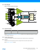
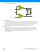
33.5.9 Analog Connections
Each comparator has up to four I/O pins that can be used as analog inputs. Each pair of comparators shares the same
four pins. These pins must be configured for analog operation before using them as comparator inputs.
Any internal reference source, such as a bandgap reference voltage or the DAC, must be configured and enabled prior to
its use as a comparator input.