
Data Sheet


88
Atmel | SMART SAM D21 [DATASHEET]
Atmel-42181G–SAM-D21_Datasheet–09/2015
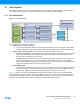
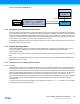
Figure 13-2. Example of SERCOM clock
13.2 Synchronous and Asynchronous Clocks
As the CPU and the peripherals can be clocked from different clock sources, possibly with widely different clock speeds,
some peripheral accesses by the CPU needs to be synchronized between the different clock domains. In these cases the
peripheral includes a SYNCBUSY status flag that can be used to check if a sync operation is in progress. As the nature
of the synchronization might vary between different peripherals, detailed description for each peripheral can be found in
the sub-chapter “synchronization” for each peripheral where this is necessary.
In the datasheet references to synchronous clocks are referring to the CPU and bus clocks, while asynchronous clocks
are clock generated by generic clocks.
13.3 Register Synchronization
There are two different register synchronization schemes implemented on this device: some modules use a common
synchronizer register synchronization scheme, while other modules use a distributed synchronizer register
synchronization scheme.
The modules using a common synchronizer register synchronization scheme are: GCLK, WDT, RTC, EIC, TC, ADC, AC,
DAC.
The modules using a distributed synchronizer register synchronization scheme are: SERCOM USART, SERCOM SPI,
SERCOM I2C, I2S, TCC, USB.
13.3.1 Common Synchronizer Register Synchronization
13.3.1.1 Overview
All peripherals are composed of one digital bus interface, which is connected to the APB or AHB bus and clocked using a
corresponding synchronous clock, and one core clock, which is clocked using a generic clock. Access between these
clock domains must be synchronized. As this mechanism is implemented in hardware the synchronization process takes
place even if the different clocks domains are clocked from the same source and on the same frequency. All registers in
the bus interface are accessible without synchronization. All core registers in the generic clock domain must be
synchronized when written. Some core registers must be synchronized when read. Registers that need synchronization
has this denoted in each individual register description. Two properties are used: write-synchronization and read-
synchronization.
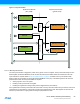
A common synchronizer is used for all registers in one peripheral, as shown in Figure 13-3. Therefore, only one register
per peripheral can be synchronized at a time.
SYSCTRL
DFLL48M
G
eneric
C
lock
G
enerator
1
G
eneric
C
lock
Multiplexer
20
SERCOM 0
Synchronous Clock
Controller
PM
CLK_SERCOM0_APB
GCLK_SERCOM0_CORE
GCLK