
Data Sheet

853
Atmel | SMART SAM D21 [DATASHEET]
Atmel-42181G–SAM-D21_Datasheet–09/2015
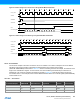
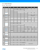
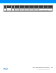
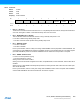
32.6.8 Oversampling and Decimation
By using oversampling and decimation, the ADC resolution can be increased from 12 bits to up to 16 bits. To increase
the resolution by n bits, 4
n
samples must be accumulated. The result must then be shifted right by n bits. This right shift is
a combination of the automatic right shift and the value written to AVGCTRL.ADJRES. To obtain the correct resolution,
the ADJRES must be configured as described in the table below. This method will result in n bit extra LSB resolution.
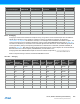
Table 32-4. Configuration Required for Oversampling and Decimation
32.6.9 Window Monitor
The window monitor allows the conversion result to be compared to some predefined threshold values. Supported
modes are selected by writing the Window Monitor Mode bit group in the Window Monitor Control register
(WINCTRL.WINMODE[2:0]). Thresholds are given by writing the Window Monitor Lower Threshold register (WINLT) and
Window Monitor Upper Threshold register (WINUT).
If differential input is selected, the WINLT and WINUT are evaluated as signed values. Otherwise they are evaluated as
unsigned values.
Another important point is that the significant WINLT and WINUT bits are given by the precision selected in the
Conversion Result Resolution bit group in the Control B register (CTRLB.RESSEL). This means that if 8-bit mode is
selected, only the eight lower bits will be considered. In addition, in differential mode, the eighth bit will be considered as
the sign bit even if the ninth bit is zero.
The INTFLAG.WINMON interrupt flag will be set if the conversion result matches the window monitor condition.
32.6.10 Offset and Gain Correction
Inherent gain and offset errors affect the absolute accuracy of the ADC. The offset error is defined as the deviation of the
actual ADC’s transfer function from an ideal straight line at zero input voltage. The offset error cancellation is handled by
the Offset Correction register (OFFSETCORR). The offset correction value is subtracted from the converted data before
writing the Result register (RESULT). The gain error is defined as the deviation of the last output step’s midpoint from the
ideal straight line, after compensating for offset error. The gain error cancellation is handled by the Gain Correction
register (GAINCORR). To correct these two errors, the Digital Correction Logic Enabled bit in the Control B register
(CTRLB.CORREN) must be written to one.
Offset and gain error compensation results are both calculated according to:
512 0x9 21 5 16 0x4 9 12 bits 32
1024 0xA 22 6 16 0x4 10 12 bits 64
Reserved 0xB –0xF 0x0 12 bits 0
Number of
Accumulated
Samples
AVGCTRL.
SAMPLENUM
Intermediate
Result
Precision
Number of
Automatic
Right Shifts
Division
Factor
AVGCTRL.
ADJRES
Total
Number
of Right
Shifts
Final
Result
Precision
Automatic
Division
Factor
Result
Resolution
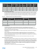
Number of Samples
to Average
AVGCTRL.SAMPLENUM[3:0]
Number of
Automatic Right
Shifts
AVGCTRL.ADJRES[2:0]
13 bits 4
1
= 4 0x2 0 0x1
14 bits 4
2
= 16 0x4 0 0x2
15 bits 4
3
= 64 0x6 2 0x1
16 bits 4
4
= 256 0x8 4 0x0