
Data Sheet

849
Atmel | SMART SAM D21 [DATASHEET]
Atmel-42181G–SAM-D21_Datasheet–09/2015
32.6.4 ADC Resolution
The ADC supports 8-bit, 10-bit and 12-bit resolutions. Resolution can be changed by writing the Resolution bit group in
the Control B register (CTRLB.RESSEL). After a reset, the resolution is set to 12 bits by default.
32.6.5 Differential and Single-Ended Conversions
The ADC has two conversion options: differential and single-ended. When measuring signals where the positive input is
always at a higher voltage than the negative input, the single-ended conversion should be used in order to have full 12-
bit resolution in the conversion, which has only positive values. The negative input must be connected to ground. This
ground could be the internal GND, IOGND or an external ground connected to a pin. Refer to INPUTCTRL for selection
details. If the positive input may go below the negative input, creating some negative results, the differential mode should
be used in order to get correct results. The configuration of the conversion is done in the Differential Mode bit in the
Control B register (CTRLB.DIFFMODE). These two types of conversion could be run in single mode or in free-running
mode. When set up in free-running mode, an ADC input will continuously sample and do new conversions. The
INTFLAG.RESRDY bit will be set at the end of each conversion.
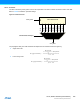
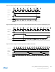
32.6.5.1 Conversion Timing
Figure 32-3 shows the ADC timing for a single conversion without gain. The writing of the ADC Start Conversion bit
(SWTRIG.START) or Start Conversion Event In bit (EVCTRL.STARTEI) must occur at least one CLK_ADC_APB cycle
before the CLK_ADC cycle on which the conversion starts. The input channel is sampled in the first half CLK_ADC
period. The sampling time can be increased by using the Sampling Time Length bit group in the Sampling Time Control
register (SAMPCTRL.SAMPLEN). Refer to Figure 32-4 for example on increased sampling time.
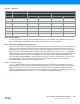
Table 32-1. Delay Gain
Delay Gain (in CLK_ADC Period)
INTPUTCTRL.GAIN[3:0]
Free-running mode Single shot mode
Name Differential Mode Single-Ended Mode Differential mode Single-Ended mode
1X 0x0 0 0 0 1
2X 0x1 0 1 0.5 1.5
4X 0x2 1 1 1 2
8X 0x3 1 2 1.5 2.5
16X 0x4 2 2 2 3
Reserved 0x5 ... 0xE Reserved Reserved Reserved Reserved
DIV2 0xF 0 1 0.5 1.5