
Data Sheet

680
Atmel | SMART SAM D21 [DATASHEET]
Atmel-42181G–SAM-D21_Datasheet–09/2015
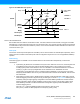
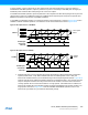
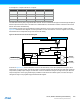
Figure 30-35.Dead-Time Generator Timing Diagram
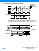
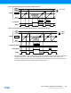
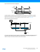
The pattern generator unit produces a synchronized bit pattern across the port pins it is connected to. The pattern
generation features are primarily intended for handling the commutation sequence in brushless DC motor (BLDC),
stepper motor and full bridge control. A block diagram of the pattern generator is shown in Figure 30-36.
Figure 30-36.Pattern Generator Block Diagram
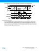
As with other double buffered timer/counter registers, the register update is synchronized to the UPDATE condition set
by the timer/counter waveform generation operation. If the synchronization is not required by the application, the
software can simply access directly the PATT.PGE, PATT.PGV bits registers.
"dti_cnt"
"OTMX output"
"DTLS"
"DTHS"
t
DTILS
t
DTIHS
T
t
P
COUNT
UPDATE
BV BVPGEB[7:0]
PGE[7:0]
PGVB[7:0]
PGV[7:0]
SWAP output
ENEN
WOx[7:0]