
Data Sheet

679
Atmel | SMART SAM D21 [DATASHEET]
Atmel-42181G–SAM-D21_Datasheet–09/2015
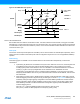
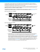
An example of 4 compare channels on 4 outputs:.
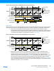
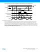
The dead-time insertion (DTI) unit generates OFF time with the non-inverted low side (LS) and inverted high side (HS) of
the WG output forced at low level. This OFF time is called dead time, and dead-time insertion ensures that the LS and
HS will never switch simultaneously.
The DTI stage consists of four equal dead-time insertion generators; one for each of the first four compare channels.
Figure 30-34
shows the block diagram of one DTI generator. The four channels have a common register which controls
the dead time and is independent of high side and low side setting.
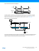
Figure 30-34.Dead-Time Generator Block Diagram
As shown in Figure 30-34, the 8-bit dead-time counter is decremented by one for each peripheral clock cycle, until it
reaches zero. A nonzero counter value will force both the low side and high side outputs into their OFF state. When the
output matrix (OTMX) output changes, the dead-time counter is reloaded according to the edge of the input. When the
output changes from low to high (positive edge) it initiates counter reload of the DTLS register, and when the output
changes from high to low (negative edge) reload the DTHS register.
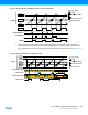
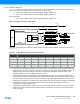
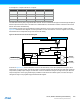
Value OTMX[3] OTMX[2] OTMX[1] OTMX[0]
0x0 CC3 CC2 CC1 CC0
0x1 CC1 CC0 CC1 CC0
0x2 CC0 CC0 CC0 CC0
0x3 CC1 CC1 CC1 CC0
Dead Time Generator
Edge Detect
DQ
= 0
"DTLS"
(To PORT)
"DTHS"
(To PORT)
Counter
EN
LOAD
OTMX output
DTLS
DTHS