
Data Sheet

670
Atmel | SMART SAM D21 [DATASHEET]
Atmel-42181G–SAM-D21_Datasheet–09/2015
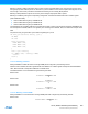
DITH5 mode:
DITH6 mode:
30.6.3.4 Ramp Operations
Three ramp operations are supported and all require the timer/counter running in single-slope PWM generation.
RAMP1 Operation
This is the default PWM operation, described in “Single-Slope PWM Generation” on page 660.
RAMP2 Operation
These operations are dedicated for PFC, Half-Brige and Push-Pull SMPS topologies, where two consecutive
timer/counter cycles are interleaved, as shown in Figure 30-20. In cycle A, odd channels output are disabled, and in cycle
B, even channels output are disabled. The ramp index changes after each update, but can be software modified using
the the Ramp index command bits in Control B Set register (CTRLBSET.IDXCMD).
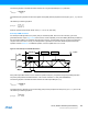
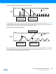
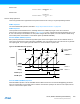
Standard RAMP2 (RAMP2) Operation
Ramp A and B periods are controlled through PER register value. Period register value can have different values on
each ramp by enabling the circular buffer option (CIPEREN). This mode allows use of a two channels TCC to generate
two output signals, or one output signal with another CC channel enabled in capture mode.
Figure 30-20.RAMP2 Standard Operation
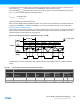
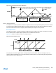
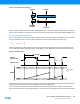
Alternate RAMP2 (RAMP2A) Operation
Alternate RAMP2 operation is similar to RAMP2 with the difference that CC0 controls both WO[0]/WO[1] waveforms
when the corresponding circular buffer option is enabled. The waveform polarity is the same on both outputs, and the
channel 1 can be used in capture mode.
PwmPulseWidth
DITHERCY
32
-------------------------------
CCx+=
PwmPulseWidth
DITHERCY
64
-------------------------------
CCx+=
COUNT
"match"
ZERO
"clear" update
A B A BRamp
WO[0]
WO[1]
TOP(A)
TOP(B)
CC0
CC1
TOP(B)
CC0
CC1
Retrigger
on
FaultA
Keep on FaultB
CIPEREN = 1
POL0 = 1
POL1 = 1
FaultA input
FaultB input