
Data Sheet

667
Atmel | SMART SAM D21 [DATASHEET]
Atmel-42181G–SAM-D21_Datasheet–09/2015
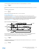
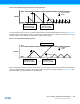
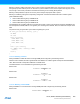
Figure 30-17.Capture Double Buffering
When the Capture x (MCx) bit and the buffer valid flag are set and a new capture event is detected, there is nowhere to
store the new timestamp. In that case the Error bit in the Interrupt Flag Status and Clear register (INTFLAG.ERR) is set.
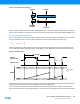
Period and Pulse-Width Capture Action
The TCC can perform two input captures and restart the counter on one of the edges. This enables the TCC to measure
the pulse-width and period. This can be used to characterize an input signal in frequency and duty cycle:
When using PPW (Period, Pulse-width) event action, period (TOP) will be captured into CC0 and pulse-width (t
p
) into
CC1. In PWP (Pulse-width, Period) event action, pulse-width (t
p
) will be captured into CC0 and period (TOP) into CC1.
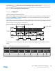
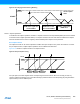
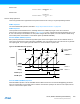
Figure 30-18.PWP Capture
Selecting PWP or PPW in the Event Action bit group in the Event Control register (EVCTRL.EVACT1) enables the TCC
to perform two capture actions, one on the rising edge and one on the falling edge.
The Timer/Counter Inverted Event 1 Input Enable bit in Event Control register (EVCTRL.TCEINV1) is used to select
which event input edge the counter restarts operation. The event source to be captured must be an asynchronous event.
BV
"capture"
IF
COUNT
CCBx
CCx
EN
EN
"INT/DMA
request"
data read
f
1
T
---
=
dutyCycle
tp
T
-----
=
Period (T)
external
signal /event
capture times
COUNT
MAX
ZERO
"capture"
Pulsewitdh (t
p
)
CC0 CC0 CC1CC1