
Data Sheet

662
Atmel | SMART SAM D21 [DATASHEET]
Atmel-42181G–SAM-D21_Datasheet–09/2015
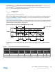
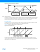
N represents the prescaler divider used. The waveform generated will have a maximum frequency of half of the TCC
clock frequency (f
GCLK_TCC
) when TOP is set to one (0x00000001) and no prescaling is used.
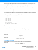
The pulse width (P
PWM_DS
) depends on the compare channel (CCx) register value and the peripheral clock frequency
(f
GCLK_TCC
), and can be calculated by the following equation:
Where N represents the prescaler divider used.
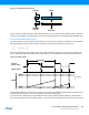
Note: In DSTOP, DSBOTTOM and DSBOTH operation, when TOP is lower than MAX/2 the CCx MSB bit defines the
ramp (rising if CCx[MSB] is 0, or falling if CCx[MSB] is 1) on which the CCx Match interrupt or event is generated.
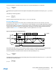
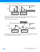
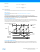
Dual-Slope Critical PWM Generation
Critical mode operation allows generation of non-aligned centered pulses. In this mode, the period time is controlled by
PER, while CCx control the generated waveform output edge during up-counting and CC(x+CC_NUM/2) control the
generated waveform output edge during down-counting.
Figure 30-10.Dual-Slope Critical Pulse Width Modulation (N=CC_NUM)
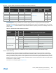
The table below shows the update counter and overflow event/interrupt generation conditions in different operation
modes.
P
PWM_DS
2N PER CCx–()⋅
f
GCLK_TCC
---------------------------------------------
=
COUNT
Period (T)
CCx
WO[x]
ZERO
TOP
MAX
"match"
"reload" update
CC(x+N/2) CCx CC(x+N/2) CCx CC(x+N/2)
Table 30-1. Counter Update and Overflow Event/Interrupt Conditions
Description Description
Name Operation Top Update
Output
Waveform
On Match
Output
Waveform
On Update
OVFIF/Event
Up Down
NFRQ Normal Frequency PER TOP/ZERO Toggle Stable TOP ZERO
MFRQ Match Frequency CC0 TOP/ZERO Toggle Stable TOP ZERO