
Data Sheet

661
Atmel | SMART SAM D21 [DATASHEET]
Atmel-42181G–SAM-D21_Datasheet–09/2015
The following equation calculates the exact resolution for a single-slope PWM (R
PWM_SS
) waveform:
The PWM frequency depends on the Period register value (PER) and the peripheral clock frequency (f
GCLK_TCC
), and can
be
calculated by the following equation:
Where N represent the prescaler divider used (1, 2, 4, 8, 16, 64, 256, 1024).
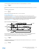
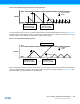
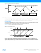
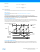
Dual-Slope PWM Generation
For dual-slope PWM generation, the period (TOP) is controlled by PER, while CCx control the duty cycle of the
generated waveform output. Figure 30-9 shows how the counter repeatedly counts from ZERO (BOTTOM) to PER and
then from PER to ZERO. The waveform generator output is set on compare match when up-counting, and cleared on
compare match when down-counting. An interrupt/event is generated on TOP and/or ZERO depend of Dual slope
operation selected Table 30-1. In DSBOTH operation, a second update time occur on TOP.
Figure 30-9. Dual-Slope Pulse Width Modulation
Using dual-slope PWM results in a lower maximum operation frequency compared to single-slope PWM generation.
The period (TOP) defines the PWM resolution. The minimum resolution is 1 bits (TOP=0x00000001).
The following equation calculates the exact resolution for dual-slope PWM (R
PWM_DS
):
The PWM frequency depends on the period setting (TOP) and the peripheral clock frequency (f
GCLK_TCC
), and can be
calculated by the following equation:
R
PWM_SS
log(TOP+1)
log(2)
-----------------------------
=
f
PWM_SS
f
GCLK_TCC
N(TOP+1)
--------------------------
=
COUNT
Period (T)
CCx=ZERO
CCx
CCx=TOP
WO[x]
ZERO
TOP
MAX
"match"
"update"
R
PWM_DS
log(PER+1)
log(2)
-----------------------------
=
f
PWM_DS
f
GCLK_TCC
2NPER⋅
--------------------------
=