
Data Sheet

659
Atmel | SMART SAM D21 [DATASHEET]
Atmel-42181G–SAM-D21_Datasheet–09/2015
TCE0 and TCE1 must be configured as asynchronous events.
30.6.2.5 Compare Operations
By default, Compare/Capture channel is configured for Compare operations. To perform capture operations, it must be
re-configured.
When using the TCC with the Compare/Capture Value registers (CCx) configured for compare operations, the counter
value is continuously compared to the values in the CCx registers. This can be used for timer or for waveform operation.
The compare buffer (CCBx) register provides double buffer capability. The double buffering synchronizes the update of
the CCx register with the buffer value at the UPDATE condition. For further details, refer to “Double Buffering” on page
663. The synchronization prevents the occurrence of odd-length, non-symmetrical pulses and ensures glitch-free output.
If Compare/Capture channel is not configured for capture operation Control A register), then compare operation will be
enabled.
Waveform Output Generation Operations
The compare channels can be used for waveform generation on output port pins. To make the waveform visible on the
connected pin, the following requirements must be fulfilled:
1. Choose a waveform generation mode in the Waveform Control register (WAVE.WAVEGEN)
2. Optionally invert the waveform output WO[x] by writing the corresponding Waveform Output Invert Enable
bit in the Driver Control register (DRVCTRL.INVENx)
3. Configure the PORT module to enable the peripheral function on the pin
The counter value is continuously compared with each CCx value. When a compare match occurs, the Match or Capture
Channel x bit in the Interrupt Flag Status and Clear register (INTFLAG.MCx) is set on the next zero-to-one transition of
CLK_TCC_COUNT. If Match/Capture occurs, interrupt can be generated when INTENSET.MCX is set. If
Compare/Match occurs, an event can be triggered when EVCTRL.MCEOx is set to one. Both interrupt and event can be
generated simultaneously. The same condition generates a DMA request.
Six waveform configurations are available through the Waveform Generation (WG) bit group in the Waveform Control
register (WAVE.WAVEGEN):
z Normal Frequency (NFRQ)
z Match Frequency (MFRQ)
z Single-slope PWM (NPWM)
z Dual-slope, interrupt/event at Top (DSTOP)
z Dual-slope, interrupt/event at ZERO (DSBOTTOM)
z Dual-slope, interrupt/event at Top and ZERO (DSBOTH)
z Dual-slope, critical interrupt/event at ZERO (DSCRITICAL)
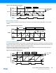
When using MFRQ, the top value is defined by the CC0 register value, for all other waveforms operation the top value is
defined by Period (PER) register value.
For dual slope waveform operations update time occurs when counter reaches the zero value. For all other waveforms
generation modes, the update time occurs on counter wraparound, on overflow, underflow or retrigger.
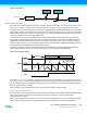
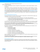
Normal Frequency Generation
For normal frequency generation, the period time is controlled by the period register (PER). The waveform generation
output (WO[x]) is toggled on each compare match between COUNT and CCx, and the corresponding Match or Capture
Channel x will be set.