
Data Sheet

629
Atmel | SMART SAM D21 [DATASHEET]
Atmel-42181G–SAM-D21_Datasheet–09/2015
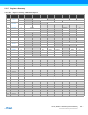
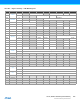
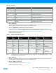
Table 29-6. Prescaler
z Bit 7 – Reserved
This bit is unused and reserved for future use. For compatibility with future devices, always write this bit to zero
when this register is written. This bit will always return zero when read.
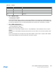
z Bits 6:5 – WAVEGEN[1:0]: Waveform Generation Operation
These bits select the waveform generation operation. They affect the top value, as shown in “Waveform Output
Operations” on page 616. It also controls whether frequency or PWM waveform generation should be used. How
these modes differ can also be seen from “Waveform Output Operations” on page 616.
These bits are not synchronized.
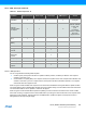
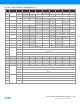
Table 29-7. Waveform Generation Operation
Note: 1. This depends on the TC mode. In 8-bit mode, the top value is the Period Value register (PER). In 16- and
32-bit mode it is the maximum value.
z Bit 4 – Reserved
This bit is unused and reserved for future use. For compatibility with future devices, always write this bit to zero
when this register is written. This bit will always return zero when read.
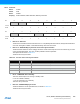
z Bits 3:2 – MODE[1:0]: TC Mode
These bits select the TC mode, as shown in Table 29-8.
These bits are not synchronized.
Value Name Description
0x0 DIV1 Prescaler: GCLK_TC
0x1 DIV2 Prescaler: GCLK_TC/2
0x2 DIV4 Prescaler: GCLK_TC/4
0x3 DIV8 Prescaler: GCLK_TC/8
0x4 DIV16 Prescaler: GCLK_TC/16
0x5 DIV64 Prescaler: GCLK_TC/64
0x6 DIV256 Prescaler: GCLK_TC/256
0x7 DIV1024 Prescaler: GCLK_TC/1024
Value Name Operation Top Value
Waveform Output
on Match
Waveform Output
on Wraparound
0x0 NFRQ Normal frequency PER
(1)
/Max Tog g l e No action
0x1 MFRQ Match frequency CC0 Tog g l e No action
0x2 NPWM Normal PWM PER
(1)
/Max
Clear when
counting up
Set when counting
down
Set when counting
up
Clear when
counting down
0x3 MPWM Match PWM CC0
Clear when
counting up
Set when counting
down
Set when counting
up
Clear when
counting down