
Data Sheet

618
Atmel | SMART SAM D21 [DATASHEET]
Atmel-42181G–SAM-D21_Datasheet–09/2015
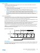
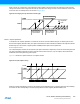
Figure 29-6. Normal PWM Operation
In match operation, Compare/Capture register CC0 is used as the top value, in this case a negative pulse will appear on
WO[0] on every overflow/underflow.
The following equation is used to calculate the exact period for a single-slope PWM (R
PWM_SS
) waveform:
where N represent the prescaler divider used (1, 2, 4, 8, 16, 64, 256, 1024).
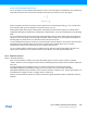
Changing the Top Value
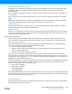
Changing the top value while the counter is running is possible. If a new top value is written when the counter value is
close to zero and counting down, the counter can be reloaded with the previous top value, due to synchronization delays.
If this happens, the counter will count one extra cycle before the new top value is used.
Figure 29-7. Changing the Top Value when Counting Down
COUNT
TOP
Period (T)
"match "
Zero
WO[x]
CCn= BOT
CC n
CCn= TOP
"wraparound "
R
PWM_SS
TOP 1+()log
2()log
-----------------------------------
=
f
PWM_SS
f
CLK_TC
NTOP 1+()
------------------------------
=
COUNT
MAX
"reload"
"write"
ZERO
New TOP value
That is higher than
Current COUNT
New TOP value
That is Lower than
Current COUNT