
Data Sheet

617
Atmel | SMART SAM D21 [DATASHEET]
Atmel-42181G–SAM-D21_Datasheet–09/2015
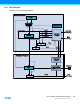
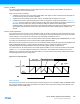
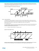
Figure 29-4. Normal Frequency Operation
When MFRQ is used, the value in CC0 will be used as the top value and WO[0] will toggle on every overflow/underflow.
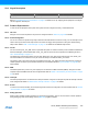
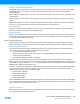
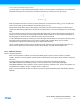
Figure 29-5. Match Frequency Operation
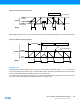
PWM Operation
In PWM operation, the CCx registers control the duty cycle of the waveform generator output. Figure 29-6 shows how in
count-up the WO[x] output is set at a start or compare match between the COUNT value and the top value and cleared
on the compare match between the COUNT value and CCx register value.
In count-down the WO[x] output is cleared at start or compare match between the COUNT value and the top value and
set on the compare match between the COUNT value and CCx register value.
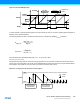
COUNT
Zero
"wraparound "
TOP
CNT written
CCx
WO[x]
COUNT
" wraparound
"
TOP
COUNT writtenDirection Change
Period (T)
Zero
WO[0]