
Data Sheet

612
Atmel | SMART SAM D21 [DATASHEET]
Atmel-42181G–SAM-D21_Datasheet–09/2015
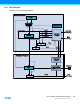
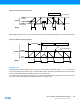
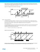
29.4 Signal Description
Refer to “I/O Multiplexing and Considerations” on page 21 for details on the pin mapping for this peripheral. One signal
can be mapped on several pins.
29.5 Product Dependencies
In order to use this peripheral, other parts of the system must be configured correctly, as described below.
29.5.1 I/O Lines
Using the TC’s I/O lines requires the I/O pins to be configured. Refer to “PORT” on page 379 for details.
29.5.2 Power Management
The TC can continue to operate in any sleep mode where the selected source clock is running. The TC interrupts can be
used to wake up the device from sleep modes. The events can trigger other operations in the system without exiting
sleep modes. Refer to “PM – Power Manager” on page 117 for details on the different sleep modes.
29.5.3 Clocks
The TC bus clock (CLK_TCx_APB, where x represents the specific TC instance number) can be enabled and disabled in
the Power Manager, and the default state of CLK_TCx_APB can be found in the Peripheral Clock Masking section in
“PM – Power Manager” on page 117.
The different TC instances are paired, even and odd, starting from TC0, and use the same generic clock, GCLK_TCx.
This means that the TC instances in a TC pair cannot be set up to use different GCLK_TCx clocks.
This generic clock is asynchronous to the user interface clock (CLK_TCx_APB). Due to this asynchronicity, accessing
certain registers will require synchronization between the clock domains. Refer to “Synchronization” on page 622 for
further details.
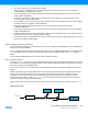
29.5.4 DMA
The DMA request lines (or line if only one request) are connected to the DMA Controller (DMAC). Using the TC DMA
requests requires the DMA Controller to be configured first. Refer to “DMAC – Direct Memory Access Controller” on page
272 for details.
29.5.5 Interrupts
The interrupt request line is connected to the Interrupt Controller. Using the TC interrupts requires the Interrupt Controller
to be configured first. Refer to “Nested Vector Interrupt Controller” on page 34 for details.
29.5.6 Events
To use the TC event functionality, the corresponding events need to be configured in the event system. Refer to “EVSYS
– Event System” on page 406 for details.
29.5.7 Debug Operation
When the CPU is halted in debug mode the TC will halt normal operation. The TC can be forced to continue operation
during debugging. Refer to the Debug Control (DBGCTRL) register for details.
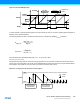
Signal Name Type Description
WO[1:0] Digital output Waveform output