
Data Sheet


597
Atmel | SMART SAM D21 [DATASHEET]
Atmel-42181G–SAM-D21_Datasheet–09/2015
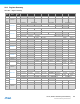
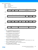
z Bit 7 – BITDELAY: Data Delay from Frame Sync
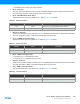
Table 28-9. Data Delay from Frame Sync
z Bits 6:5 – FSWIDTH[1:0]: Frame Sync Width
This field selects the duration of the Frame Sync output pulses.
When not in Burst mode, the Clock unit n operates in continuous mode when enabled, with periodic Frame Sync
pulses and Data samples. Refer to Table 28-10 for details.
In Burst mode, a single Data transfer starts at each Frame Sync pulse; these pulses are 1-bit wide and occur only
when a Data transfer is requested. Note that the compact stereo modes (16C and 8C) are not supported in the
Burst mode.
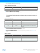
Table 28-10. Frame Sync Width
z Bits 4:2 – NBSLOTS[2:0]: Number of Slots in Frame
Each Frame for Clock Unit n is composed of (NBSLOTS + 1) Slots.
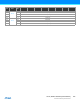
z Bits 1:0 – SLOTSIZE[1:0]: Slot Size
Each Slot for Clock Unit n is composed of a number of bits specified by SLOTSIZE. Refer to Table 28-11 for
details.
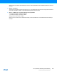
Table 28-11. Slot Size
BITDELAY Name Description
0x0 LJ Left Justified (0 Bit Delay)
0x1 I2S I2S (1 Bit Delay)
FSWIDTH[1:0] Name Description
0x0 SLOT Frame Sync Pulse is 1 Slot wide (default for I2S protocol)
0x1 HALF Frame Sync Pulse is half a Frame wide
0x2 BIT Frame Sync Pulse is 1 Bit wide
0x3 BURST
Clock Unit n operates in Burst mode, with a 1-bit wide Frame
Sync pulse per Data sample, only when Data transfer is
requested
SLOTSIZE[1:0] Name Description
0x0 8 8-bit Slot for Clock Unit n
0x1 16 16-bit Slot for Clock Unit n
0x2 24 24-bit Slot for Clock Unit n
0x3 32 32-bit Slot for Clock Unit n