
Data Sheet

576
Atmel | SMART SAM D21 [DATASHEET]
Atmel-42181G–SAM-D21_Datasheet–09/2015
Refer to Table 6-1 in the “I/O Multiplexing and Considerations” on page 21 for details on the pin mapping for this
peripheral. One signal can be mapped on several pins.
28.5 Product Dependencies
In order to use this module, other parts of the system must be configured correctly, as described below.
28.5.1 I/O lines
Using I
2
S’s I/O lines requires the I/O pins to be configured. Refer to the “PORT” on page 379 chapter for details.
The I
2
S pins may be multiplexed with I/O Controller lines. The user must first program the I/O Controller to assign the
desired I
2
S pins to their peripheral function. If the I
2
S I/O lines are not used by the application, they can be used for other
purposes by the I/O Controller. It is required to enable only the I
2
S inputs and outputs actually in use.
28.5.2 Power Management
The I
2
S will continue to operate in any sleep mode where the selected source clocks are running.
28.5.3 Clocks
The clock for the I
2
S bus interface (CLK_I2S_APB) is generated by the Power Manager. This clock is disabled at reset,
and can be enabled in the Power Manager. It is recommended to disable the I
2
S before disabling the clock, to avoid
freezing the I
2
S in an undefined state.
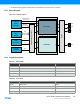
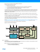
There are two generic clocks, GCLK_I2S_0 and GCLK_I2S_1 connected the I
2
S peripheral, one for each I
2
S clock unit.
The generic clocks (GCLK_I2S_n, n=0..1) can be set to a wide range of frequencies and clock sources. The
GCLK_I2S_n must be enabled and configured before use. Refer to the “GCLK – Generic Clock Controller” on page 95
section for details on the generic clocks used for the I
2
S.
The generic clocks are only used in Master mode and Controller mode. In Master mode, the clock from a single clock unit
can be used for both Serializers to handle synchronous transfers, or a separate clock from different clock units can be
used for each Serializer to handle transfers on non-related clocks.
28.5.4 DMA
The DMA request lines are connected to the DMA Controller (DMAC). Using the I
2
S DMA requests requires the DMA
Controller to be configured first. Refer to “DMAC – Direct Memory Access Controller” on page 272 for details.
28.5.5 Interrupts
The interrupt request line is connected to the interrupt controller. Using the I
2
S interrupts requires the interrupt controller
to be configured first. Refer to “Nested Vector Interrupt Controller” on page 34 for details.
28.5.6 Events
Not applicable.
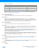
Table 28-3. Controller Mode
Pin Name Pin Description Type
MCKn Master Clock for Clock Unit n Output
SCKn Serial Clock for Clock Unit n Output
FSn I
2
S Word Select or TDM Frame Sync Output
SDm Not Applicable Not Applicable