
Data Sheet

524
Atmel | SMART SAM D21 [DATASHEET]
Atmel-42181G–SAM-D21_Datasheet–09/2015
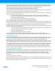
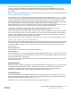
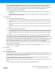
Figure 27-11.Slave Behavioral Diagram (SCLSM=1)
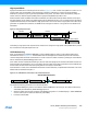
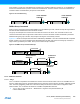
Receiving Address Packets (SCLSM=0)
When SCLSM is zero, the I
2
C slave stretches the SCL line according to Figure 27-10. When the I
2
C slave is properly
configured, it will wait for a start condition to be detected. When a start condition is detected, the successive address
packet will be received and checked by the address match logic. If the received address is not a match, the packet is
rejected and the I
2
C slave waits for a new start condition. The I
2
C slave Address Match bit in the Interrupt Flag register
(INTFLAG.AMATCH) is set when a start condition followed by a valid address packet is detected. SCL will be stretched
until the I
2
C slave clears INTFLAG.AMATCH. Because the I
2
C slave holds the clock by forcing SCL low, the software is
given unlimited time to respond to the address.
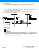
The direction of a transaction is determined by reading the Read / Write Direction bit in the Status register
(STATUS.DIR), and the bit will be updated only when a valid address packet is received.
If the Transmit Collision bit in the Status register (STATUS.COLL) is set, this indicates that the last packet addressed to
the I
2
C slave had a packet collision. A collision causes the SDA and SCL lines to be released without any notification to
software. The next AMATCH interrupt is, therefore, the first indication of the previous packet’s collision. Collisions are
intended to follow the SMBus Address Resolution Protocol (ARP).
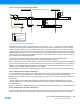
After the address packet has been received from the I
2
C master, one of two cases will arise based on transfer direction.
Case 1: Address packet accepted – Read flag set
The STATUS.DIR bit is one, indicating an I
2
C master read operation. The SCL line is forced low, stretching the bus clock.
If an ACK is sent, I
2
C slave hardware will set the Data Ready bit in the Interrupt Flag register (INTFLAG.DRDY),
indicating data are needed for transmit. If not acknowledge is sent, the I
2
C slave will wait for a new start condition and
address match.
Typically, software will immediately acknowledge the address packet by sending an ACK/NACK bit. The I
2
C slave
command CTRLB.CMD = 3 can be used for both read and write operation as the command execution is dependent on
the STATUS.DIR bit.
Writing a one to INTFLAG.AMATCH will also cause an ACK/NACK to be sent corresponding to the CTRLB.ACKACT bit.
Case 2: Address packet accepted – Write flag set
The STATUS.DIR bit is cleared, indicating an I
2
C master write operation. The SCL line is forced low, stretching the bus
clock. If an ACK is sent, the I
2
C slave will wait for data to be received. Data, repeated start or stop can be received.
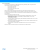
S
S3
ADDRESS
S2
R
W
DATA A/A
DATA
P
S2
Sr
S3
P
S2
Sr
S3
SLAVE ADDRESS INTERRUPT
SLAVE DATA INTERRUPT
S
W
S
W
S
W
A/A
S
W
Interrupt on STOP
Condition Enabled
S1
SLAVE STOP INTERRUPT
S
W
Software interaction
The master provides data
on the bus
Addressed slave provides
data on the bus
A/A
A/A
SLAVE DATA INTERRUPT in Master read mode
)