
Data Sheet


511
Atmel | SMART SAM D21 [DATASHEET]
Atmel-42181G–SAM-D21_Datasheet–09/2015
27. SERCOM I
2
C – SERCOM Inter-Integrated Circuit
27.1 Overview
The inter-integrated circuit (I
2
C) interface is one of the available modes in the serial communication interface (SERCOM).
Refer to “SERCOM – Serial Communication Interface” on page 432 for details.
The I
2
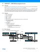
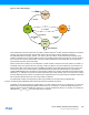
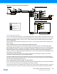
C interface uses the SERCOM transmitter and receiver configured as shown in Figure 27-1. Fields shown in capital
letters are registers accessible by the CPU, while lowercase fields are internal to the SERCOM. Each side, master and
slave, depicts a separate I
2
C interface containing a shift register, a transmit buffer and a receive buffer. In addition, the
I
2
C master uses the SERCOM baud-rate generator, while the I
2
C slave uses the SERCOM address match logic.
27.2 Features
z Master or slave operation
z Can be used with DMA
z Philips I
2
C compatible
z SMBus
™
compatible
z PMBus compatible
z 100kHz and 400kHz, 1MHz and 3.4MHz support at low system clock frequencies
z Physical interface includes:
z Slew-rate limited outputs
z Filtered inputs
z Slave operation:
z Operation in all sleep modes
z Wake-up on address match
z 7-bit and 10-bit Address match in hardware for:
z Unique address and/or 7-bit general call address
z Address range
z Two unique addresses can be used with DMA
27.3 Block Diagram
Figure 27-1. I
2
C Single-Master Single-Slave Interconnection
shift register shift register
Master Slave
SDA
SCL
Tx DATA
Rx DATA
Tx DATA
Rx DATA ==
ADDR/ADDRMASKBAUD
baud rate generator
0
0
0
0
SCL low hold
S
C
L
l
o
w
o
o
h
o
l
d
SCL low hold