
Data Sheet

486
Atmel | SMART SAM D21 [DATASHEET]
Atmel-42181G–SAM-D21_Datasheet–09/2015
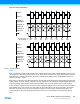
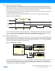
Figure 26-6. Multiple Slaves in Series
26.6.3.4 Loop-back Mode
By configuring the Data In Pinout (CTRLA.DIPO) and Data Out Pinout (CTRLA.DOPO) to use the same data pins for
transmit and receive, loop-back is achieved. The loop-back is through the pad, so the signal is also available externally.
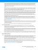
26.6.3.5 Hardware Controlled _SS
In master mode, a single _SS chip select can be controlled by hardware by setting the Master Slave Select Enable
(CTRLB.MSSEN) bit to one. In this mode, the _SS pin is driven low for a minimum of one baud cycle before transmission
begins, and stays low for a minimum of one baud cycle after transmission completes. If back-to-back frames are
transmitted, the _SS pin will always be driven high for a minimum of one baud cycle between frames.
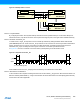
In Figure 26-7, the time T is between one and two baud cycles depending on the SPI transfer mode.
Figure 26-7. Hardware Controlled _SS
When MSSEN is set to zero, the _SS pin(s) is/are controlled by user software and normal GPIO.
26.6.3.6 Slave Select Low Detection
In slave mode the SPI is capable of waking the CPU when the slave select (_SS) goes low. When the Slave Select Low
Detect is enabled (CTRLB.SSDE=1), a high to low transition will set the Slave Select Low interrupt flag (INTFLAG.SSL)
and the device will wake if applicable.
shift register shift register
MOSI
MISO
SCK
_SS
MOSI
MISO
_SS
SCK
shift register
MOSI
MISO
_SS
SCK
SPI Master SPI Slave 0
SPI Slave n-1
_SS
SCK
T
T = 1 to 2 baud cycles
T
T
T
T