
Data Sheet


478
Atmel | SMART SAM D21 [DATASHEET]
Atmel-42181G–SAM-D21_Datasheet–09/2015
26. SERCOM SPI – SERCOM Serial Peripheral Interface
26.1 Overview
The serial peripheral interface (SPI) is one of the available modes in the Serial Communication Interface (SERCOM).
Refer to “SERCOM – Serial Communication Interface” on page 432 for details.
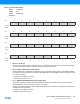
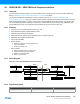
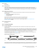
The SPI uses the SERCOM transmitter and receiver configured as shown in “Full-Duplex SPI Master Slave
Interconnection” on page 478. Each side, master and slave, depicts a separate SPI containing a shift register, a transmit
buffer and two receive buffers. In addition, the SPI master uses the SERCOM baud-rate generator, while the SPI slave
can use the SERCOM address match logic. Fields shown in capital letters are synchronous to CLK_SERCOMx_APB
and accessible by the CPU, while fields with lowercase letters are synchronous to the SCK clock.
26.2 Features
z Full-duplex, four-wire interface (MISO, MOSI, SCK, _SS)
z Single-buffered transmitter, double-buffered receiver
z Supports all four SPI modes of operation
z Single data direction operation allows alternate function on MISO or MOSI pin
z Selectable LSB- or MSB-first data transfer
z Can be used with DMA
z Master operation:
z Serial clock speed up to half the system clock
z 8-bit clock generator
z Hardware controlled _SS
z Slave operation:
z Serial clock speed up to the system clock
z Optional 8-bit address match operation
z Operation in all sleep modes
z Wake on _SS transition
26.3 Block Diagram
Figure 26-1. Full-Duplex SPI Master Slave Interconnection
26.4 Signal Description
shift register shift register
Master Slave
MISO
MOSI
SCK
_SS
Tx DATA
rx buffer
Rx DATA
Tx DATA
rx buffer
Rx DATA
==
ADDR/ADDRMASKBAUD
baud rate generator
Address Match
Signal Name Type Description
PAD[3:0] Digital I/O General SERCOM pins