
Data Sheet


441
Atmel | SMART SAM D21 [DATASHEET]
Atmel-42181G–SAM-D21_Datasheet–09/2015
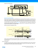
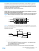
25.3 Block Diagram
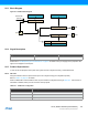
Figure 25-1. USART Block Diagram
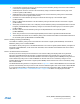
25.4 Signal Description
Please refer to “I/O Multiplexing and Considerations” on page 21 for details on the pin mapping for this peripheral. One
signal can be mapped on several pins.
25.5 Product Dependencies
In order to use this peripheral, other parts of the system must be configured correctly, as described below.
25.5.1 I/O Lines
Using the USART’s I/O lines requires the I/O pins to be configured using port configuration (PORT).
Refer to “PORT” on page 379 for details.
When the SERCOM is used in USART mode, the pins should be configured according to Table 25-1. If the receiver or
transmitter is disabled, these pins can be used for other purposes.
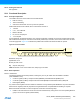
Table 25-1. USART Pin Configuration
TxD
RxD
XCK
rx shift register
TX DATA
tx shift register
rx buffer
RX DATA
status
STATUS
BAUD
baud rate generator
Internal Clk
(GCLK)
/1 - /2 - /16
Signal name
Signal Name Type Description
PAD[3:0] Digital I/O General SERCOM pins
Pin Pin Configuration
TxD Output
RxD Input
XCK Output or input