
Data Sheet

435
Atmel | SMART SAM D21 [DATASHEET]
Atmel-42181G–SAM-D21_Datasheet–09/2015
24.6.2 Basic Operation
24.6.2.1 Initialization
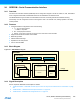
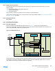
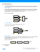
The SERCOM must be configured to the desired mode by writing to the Operating Mode bits in the Control A register
(CTRLA.MODE). Refer to Figure 24-1 for details.
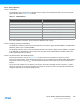
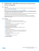
Table 24-1. SERCOM Modes
For further initialization information, see the respective SERCOM mode chapters.
24.6.2.2 Enabling, Disabling and Resetting
The SERCOM is enabled by writing a one to the Enable bit in the Control A register (CTRLA.ENABLE). The SERCOM is
disabled by writing a zero to CTRLA.ENABLE.
The SERCOM is reset by writing a one to the Software Reset bit in the Control A register (CTRLA.SWRST). All registers
in the SERCOM, except DBGCTRL, will be reset to their initial state, and the SERCOM will be disabled. Refer to the
CTRLA register descriptions for details.
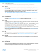
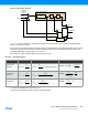
24.6.2.3 Clock Generation – Baud-Rate Generator
The baud-rate generator, as shown in Figure 24-3, is used for internal clock generation for asynchronous and
synchronous communication. The generated output frequency (f
BAUD
) is determined by the Baud register (BAUD) setting
and the baud reference frequency (f
REF
). The baud reference clock is the serial engine clock, and it can be internal or
external.
For asynchronous operation, the /16 (divide-by-16) output is used when transmitting and the /1 (divide-by-1) output is
used when receiving. For synchronous operation the /2 (divide-by-2) output is used. This functionality is automatically
configured, depending on the selected operating mode.
CTRLA.MODE Description
0x0 USART with external clock
0x1 USART with internal clock
0x2 SPI in slave operation
0x3 SPI in master operation
0x4 I
2
C slave operation
0x5 I
2
C master operation
0x6-0x7 Reserved